

Commissioning
Checks Before Power-On
| No. | Check Item | Acceptance Criteria |
| 1 | Installation/Mounting environment | The installation environment is safe and the unit has adequate clearance as per the instruction in this manual as well as in compliance with local standards. The area around the installation should be free from clutter and should not be flood-prone. |
| 2 | Battery and inverter mounting | The battery and inverter should be mounted correctly, securely, and reliably. |
| 3 | Wi-Fi mounting | The Wi-Fi Dongle should be mounted correctly, securely, and reliably. |
| 4 | Cable layout | Cables should be routed neatly and protected adequately where exposed, in accordance with standards. |
| 5 | Cable tie | Cable ties should be secured and trimmed evenly and no burr exists. |
| 6 | Grounding | The grounding cables should be connected correctly, securely, and reliably. Impedance/resistance checks should be conducted to confirm reliable Earth connections. |
| 7 | Switches and circuit breakers status | The PV switch (if there is any) and battery circuit breakers and any AC circuit breakers connecting to the energy storage system should be OFF. |
| 8 | Cable connections | The AC cables, PV cables (if there are any), battery power cables, and communication cables should be connected correctly, securely, and reliably. |
| 9 | Unused ports | Unused power ports and communication ports should be sealed from water or dust ingress by watertight caps. |
Power ON the Product
WARNING
- Before doing the electrical connection, please ensure the PV switch & all AC and BAT circuit breakers in the system are switched OFF and cannot be reactivated.
- Never power on the energy storage system without the correct and reliable installation and electrical connection.
Check the grid's allowed voltage range and frequency range and the installation (including location, direction and phase sequence) of all CT(s) and/or meter(s).
Switch on the battery circuit breaker at the left of the energy storage inverter.
Switch on the battery circuit breakers of all batteries.
Switch on the external AC circuit breaker between the grid and the energy storage inverter.
Please strictly follow the aforementioned steps to power on the system.
Download The AlphaPartner And Registration
WARNING
- Only Installer Organisation Self-register via the APP; One person, one organisation, one role(One account corresponds to one role within an organisation).
The country / region determines the Data Centre and Review Rules: AU / NZ If the criteria are met, APProval is automatic, Non-AU go through manual review.
Download and Install the APP
AlphaESS Partner APP is a dedicated mobile Application for distributors, installer companies, installers and other partners.It supports assigning separate accounts to administrators, installers and other organisational roles. This avoids shared accounts, improves management accuracy, and reduces security risks.
AlphaESS Partner APP can help you complete installation, after-sales service and commissioning.
It also provides digital services such as organisation management, online communication, installation guidance and an online store.
| AlphaPartner for Android | AlphaPartner for iOS |
|---|---|
 | 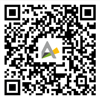 |
Figure 8-1 QR codes for downloading the AlphaPartner APP
Register as an Installer
Step 1:Open the Partner APP and, on the login page, tap “Register”.
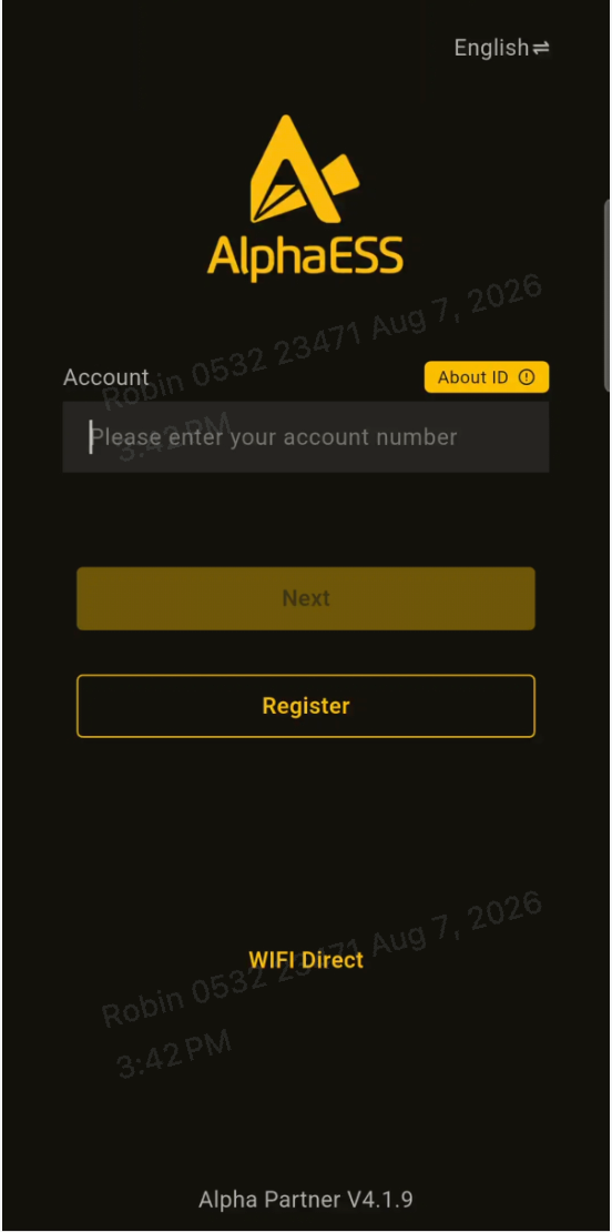
Figure 8-2 Step 1: Tap "Register" on the Partner APP login page
Step 2:Select Country / Region (Determines the data center and review rules according to the actual place of business).
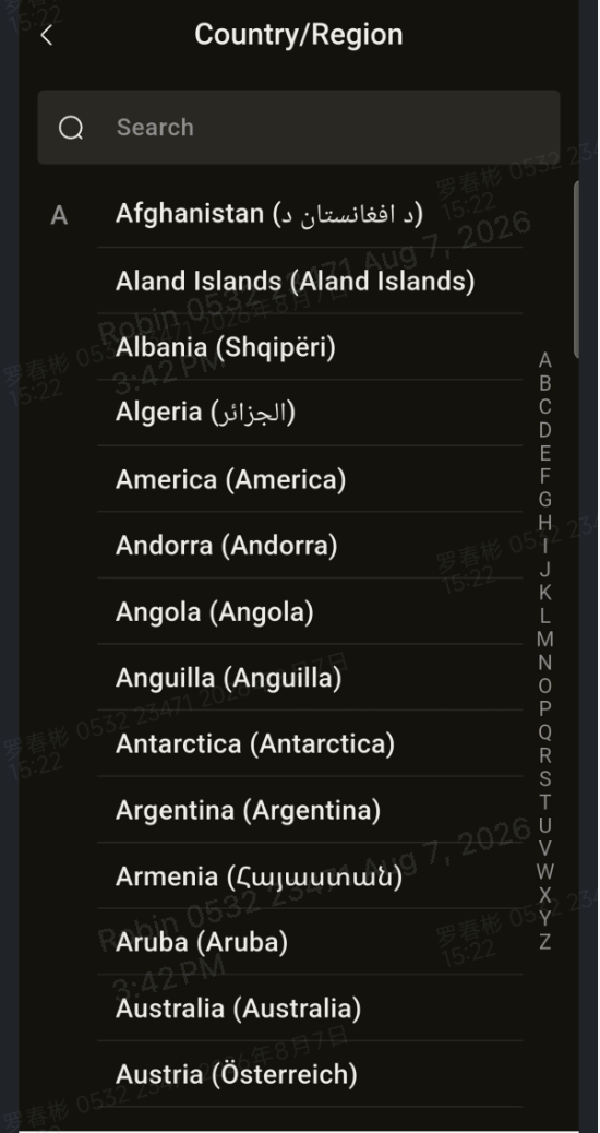
Figure 8-3 Step 2: Select the country/region
Step 3:Enter Organisation Information: organisation name, country, address, and ABN / Business Licence Number(mandatory depending on the country classification; after submission verification).
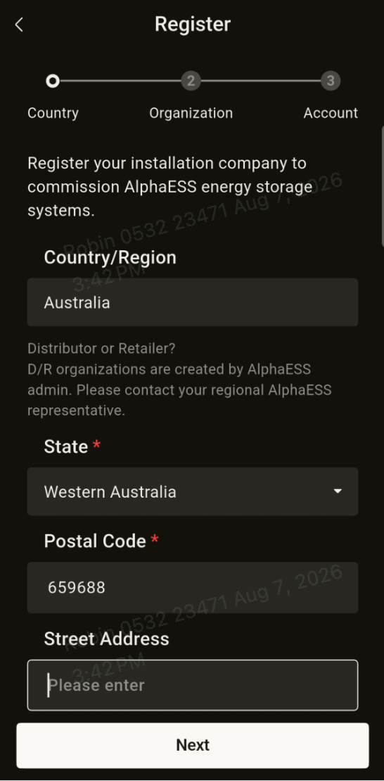
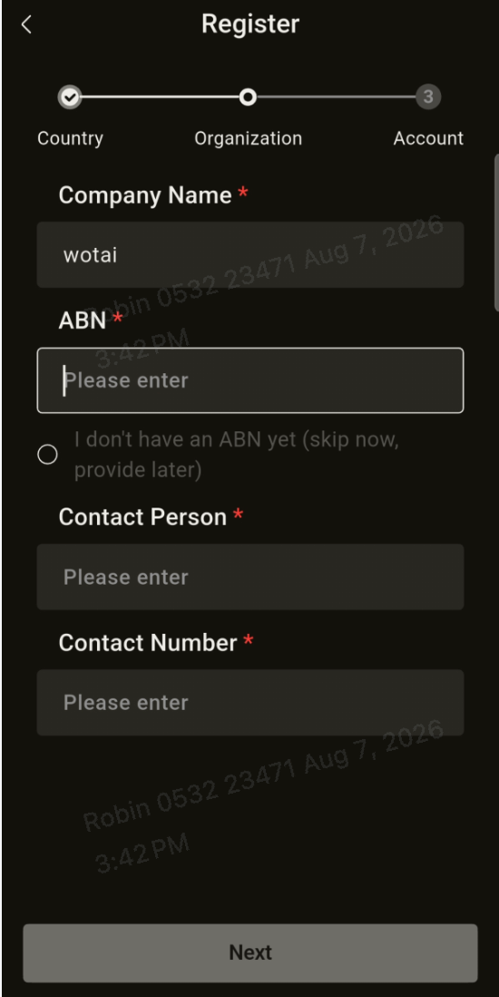
Figure 8-4 Step 3: Enter the organisation information
Step 4:Enter Account Information: Email, Verification Code (email verification code), Password, Confirm Password.
Tick the terms and consent checkbox, then tap “Register / Submit” to submit.
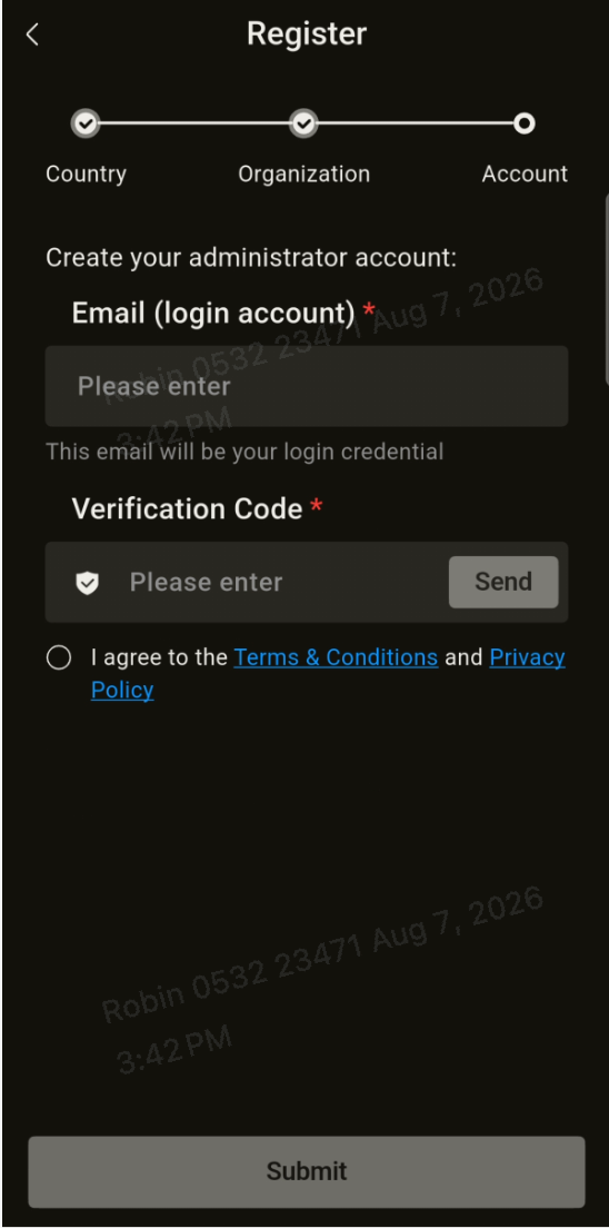
Figure 8-5 Step 4: Enter the account information and submit the registration
Review Result and Activation
AU / NZ: If the criteria are met approved automatically, you can log in directly.
Non-AU: Enter manual review, with the result notified by email—approved or rejected (including the rejection reason);
No additional emails will be sent while the review is pending.
After approval, log in with the registered account.
Account Login And Workspace Selection
Account Login
Step 1:Login Page Input Email and Password, tap “Login”; or switch to “Login with Code” to log in with the email verification code.
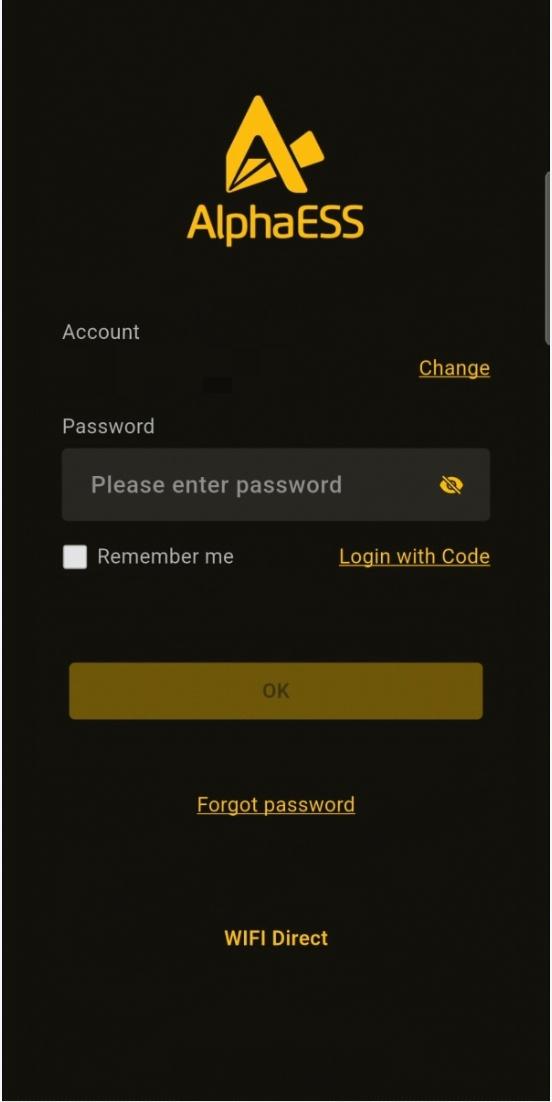
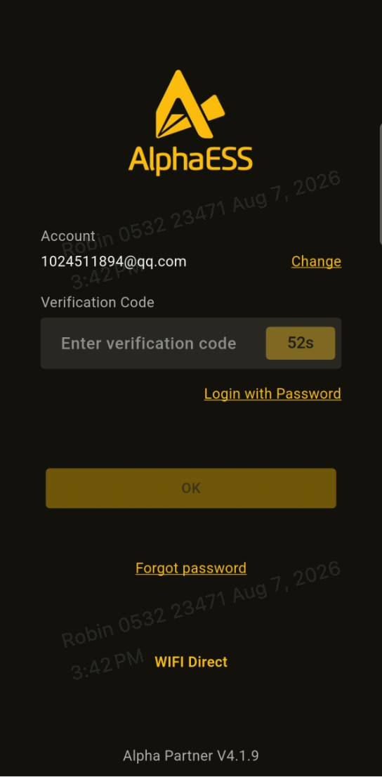
Figure 8-6 Step 1: Log in with the account password or the email verification code
Step 2:If you forget your password, tap “Forgot Password” to reset it via the email verification code.
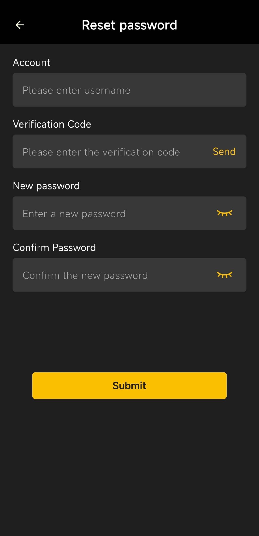
Figure 8-7 Step 2: Reset the password with the email verification code
Select And Switch Workspace
One account can belong to multiple organisations, and within the same organisation has one role.
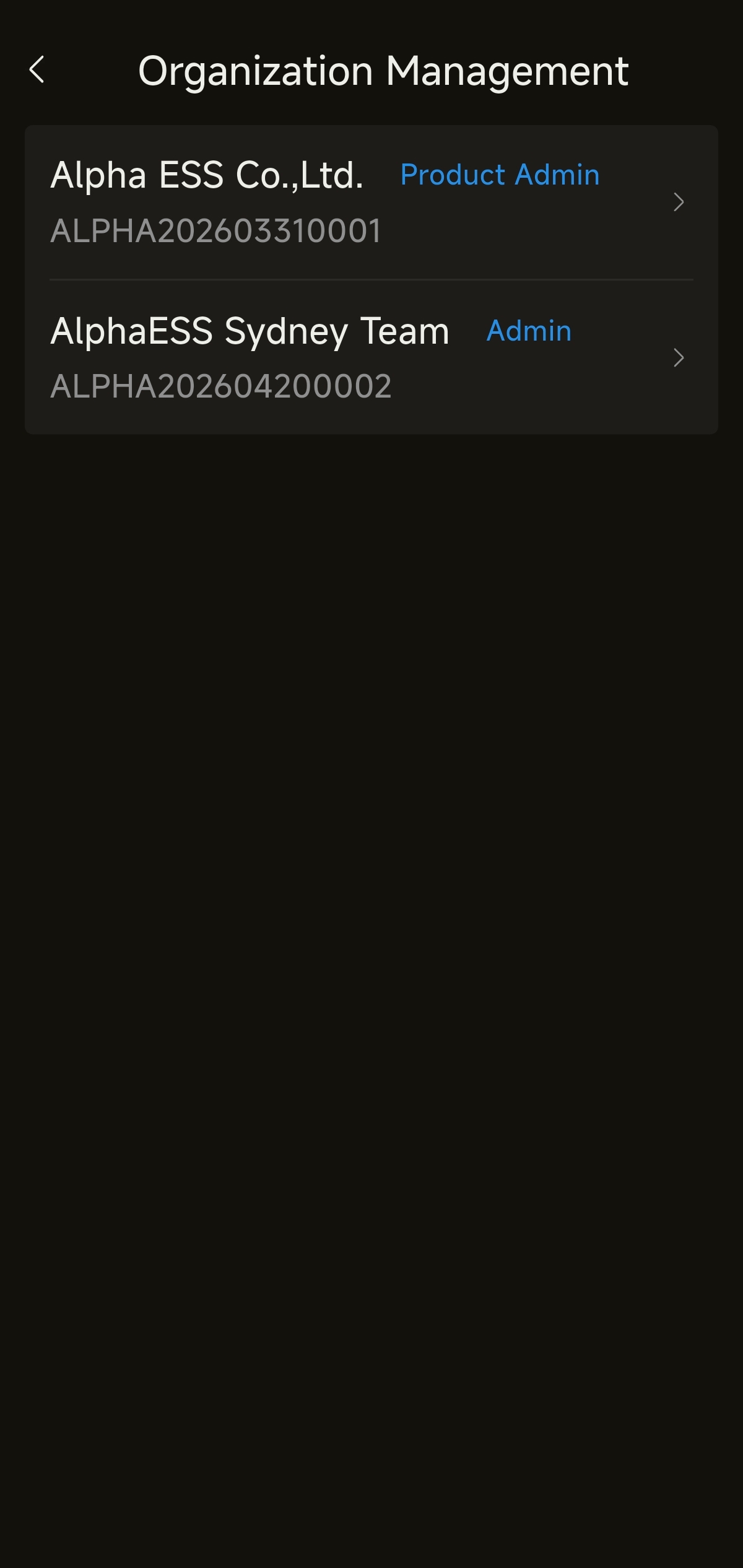
Figure 8-8 Organisation and role list of the account
You can switch at any time in the APP Organisation / Role, after switching, the interface and permissions refresh according to the selected workspace.
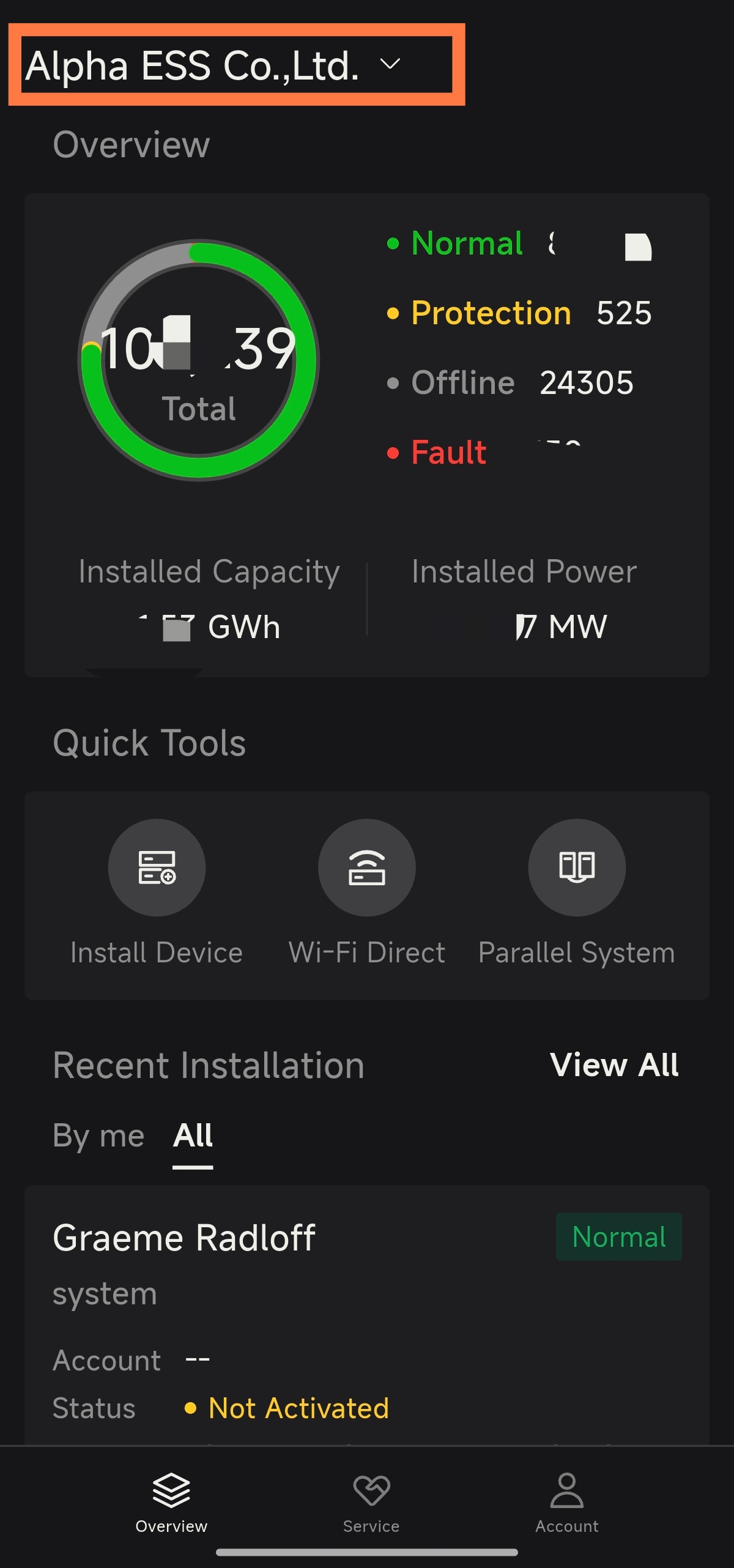
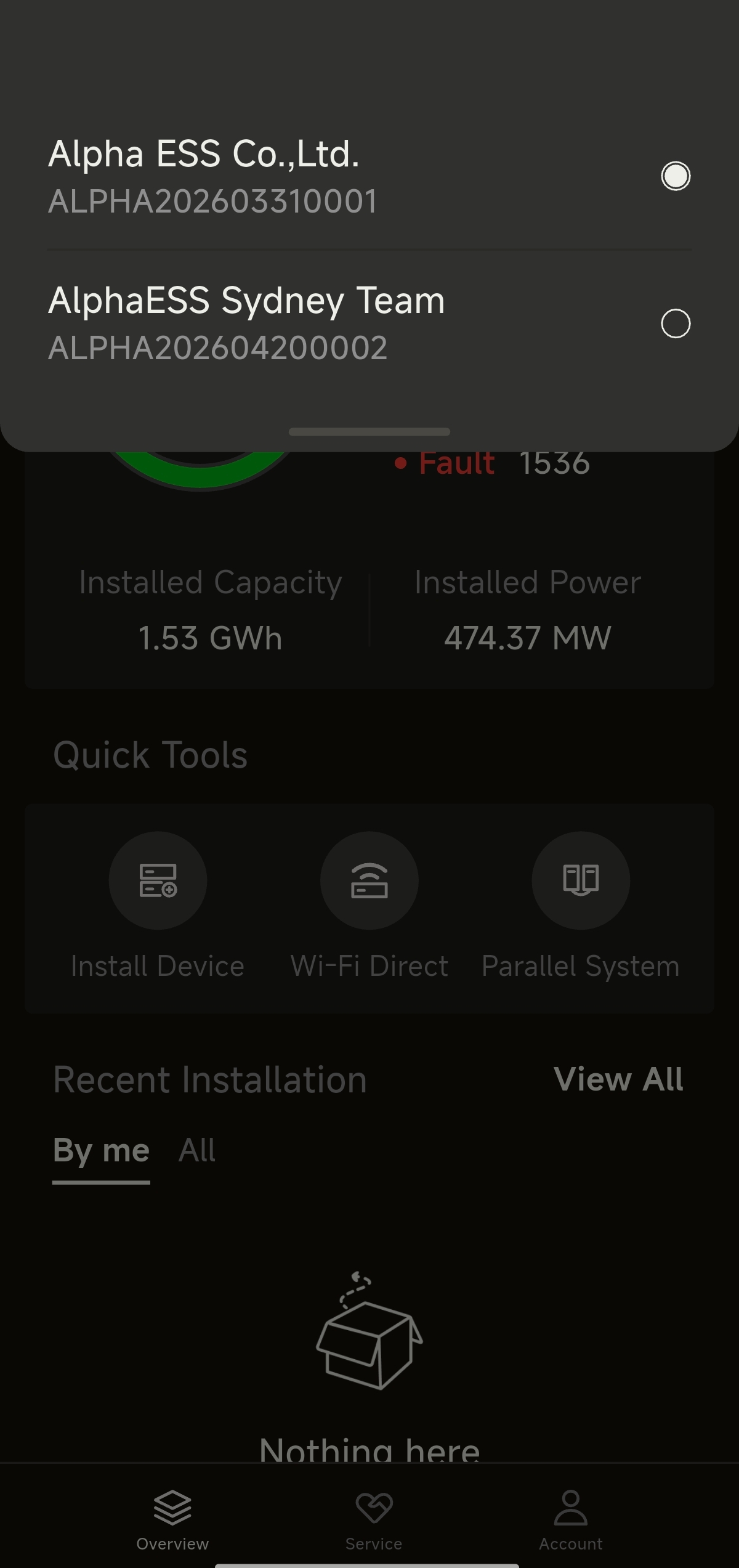
Figure 8-9 Workspace overview pages after switching the organisation/role
Installation, Network Configuration & Commissioning
Standalone Installation
Prerequisites
Device Side: The energy storage unit is powered on, and the Wi-Fi communication stick is plugged in,The POWER indicator light is steadily on.
Home Router: The network name and password are known, 2.4GHz The band is enabled, and the signal covers the device installation location.
Phone: Wi-Fi and Bluetooth are both enabled, location permission has been granted (required for Android Wi-Fi scanning and silent connection), and the person is standing within a few meters of the device.
Phone Internet Connection: It is recommended to enable mobile data — when falling back to direct AP connection, the phone will temporarily switch to the device hotspot and disconnect from the internet.
Network Configuration
Step 1:Tap Quick Tools — Install Device
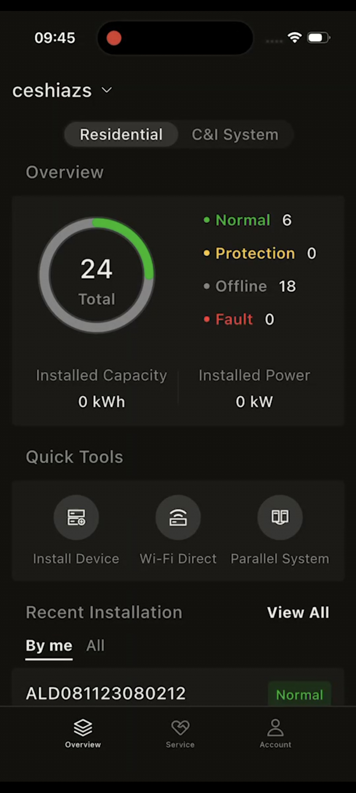
Figure 8-10 Step 1: Tap "Quick Tools - Install Device" on the APP home page
Step 2:Bluetooth automatically scans nearby devices, usually devices starting with “AL”, matching the device SN. (If the device does not support the Bluetooth function, it cannot be found during search. In this case, please select to connect the device by scanning the device SN).
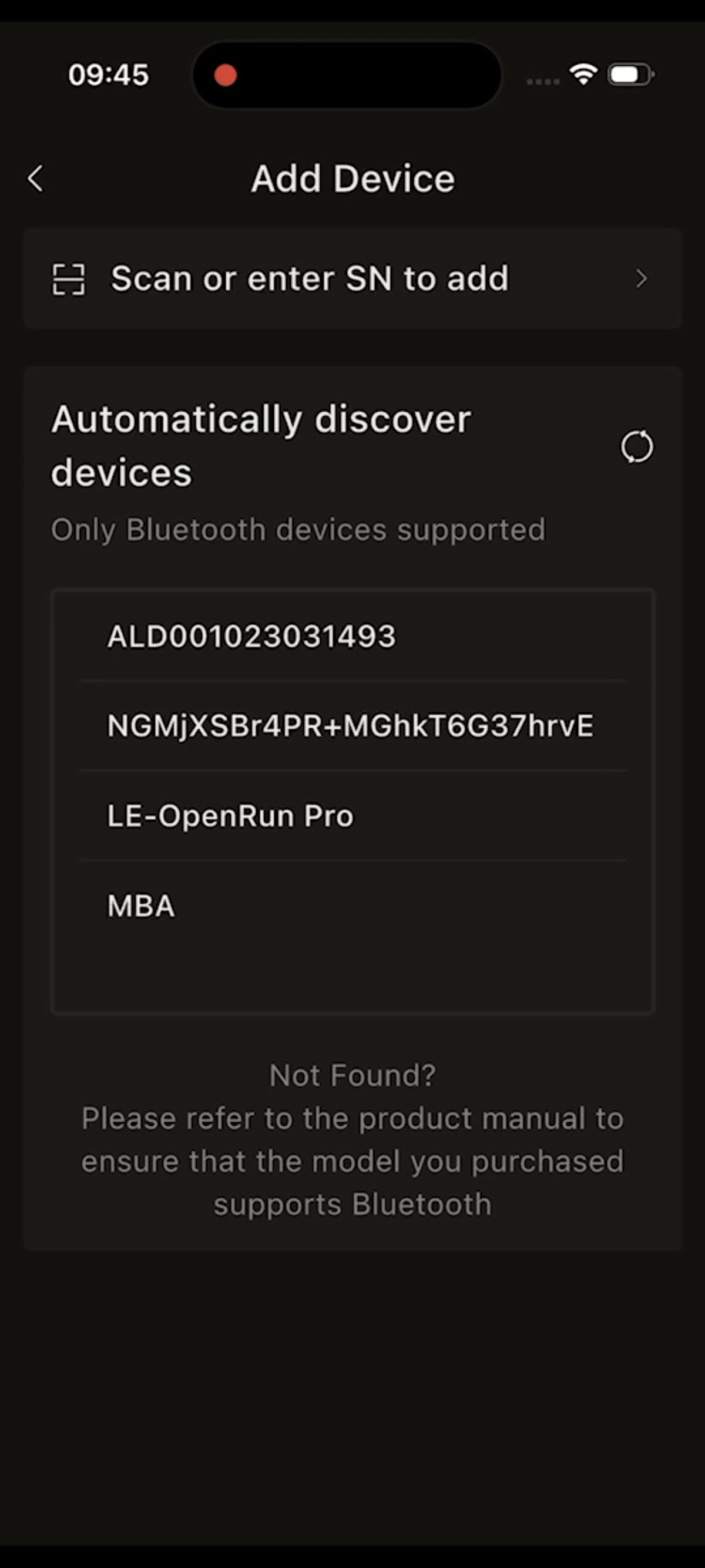
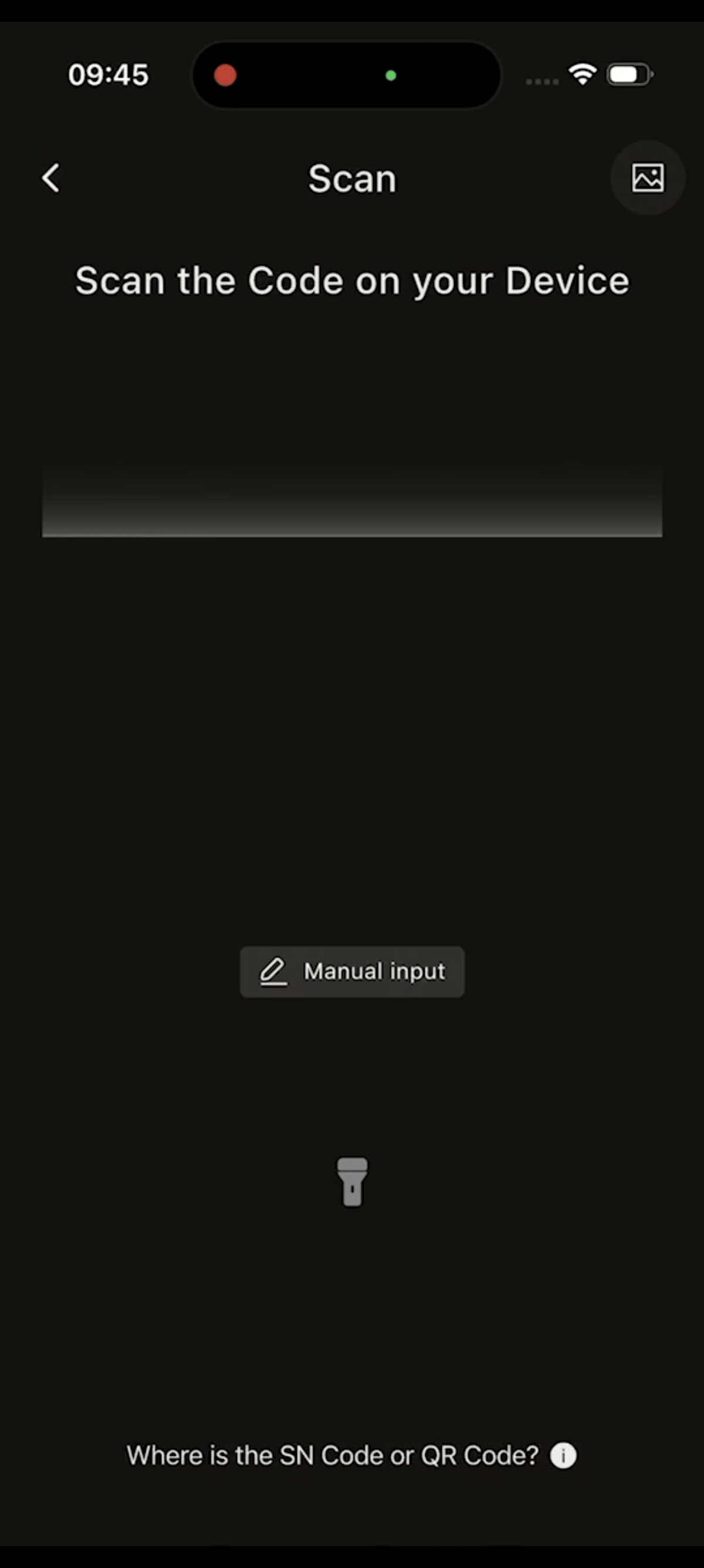
Figure 8-11 Step 2: Scan or automatically discover the device via Bluetooth
Please refer to the following for the physical location of the scannable SN label on the device.
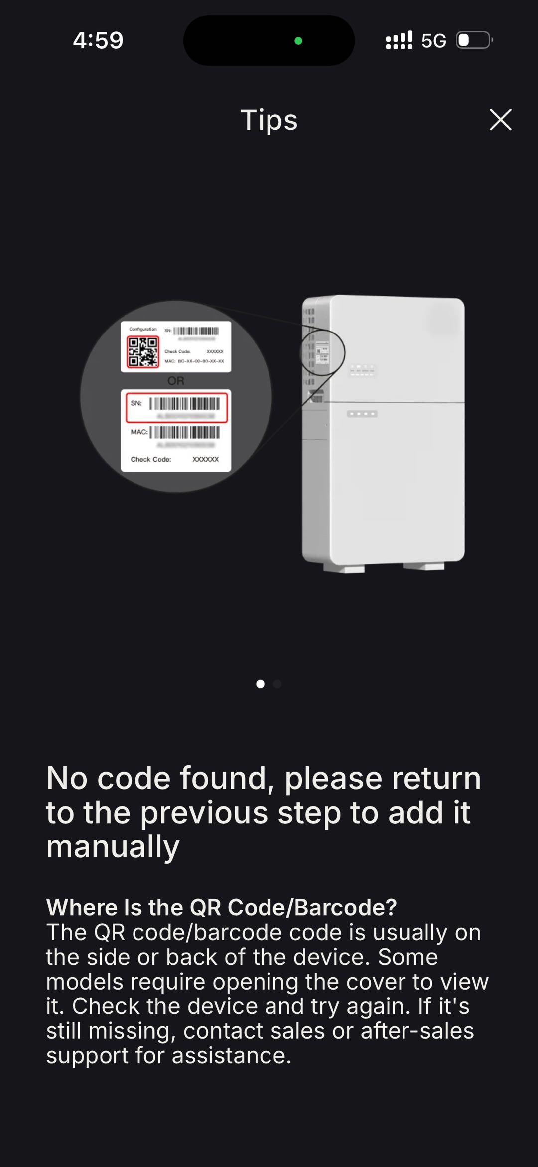
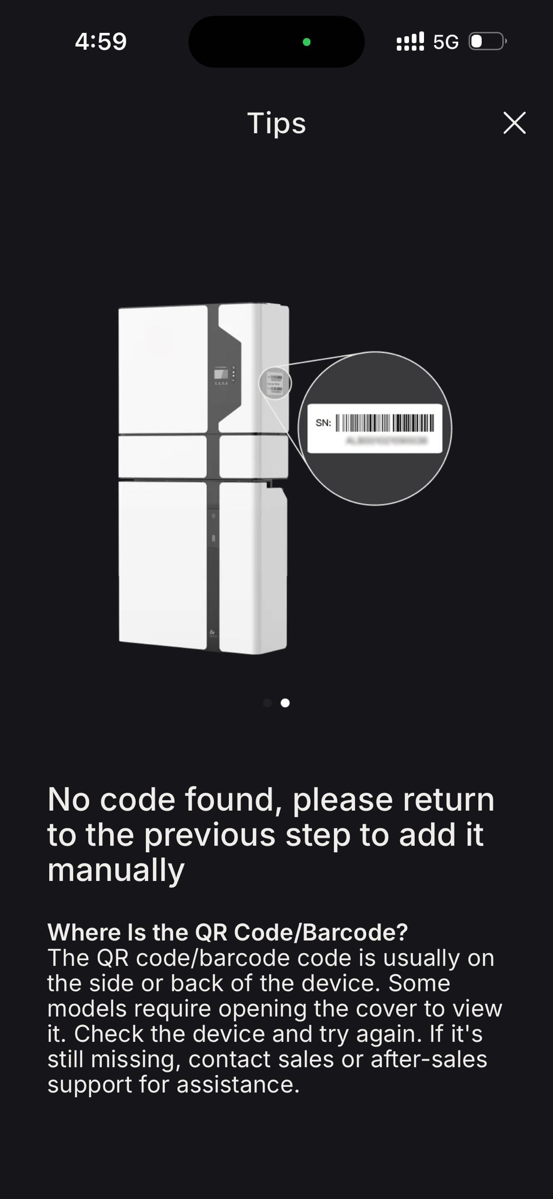
Figure 8-12 Location of the SN/QR code label on the device
Step 3:Select the device found via Bluetooth, and enter the device check code. The APP will redirect to the "Confirm device info" screen. Verify the information and click Next.
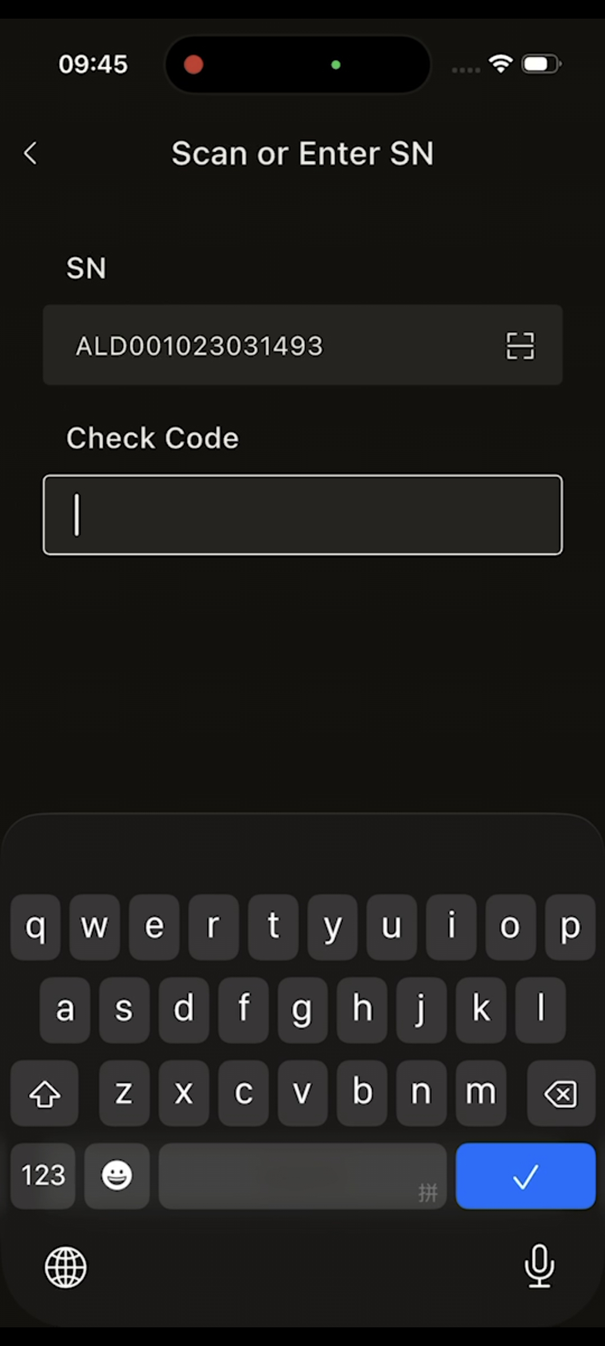
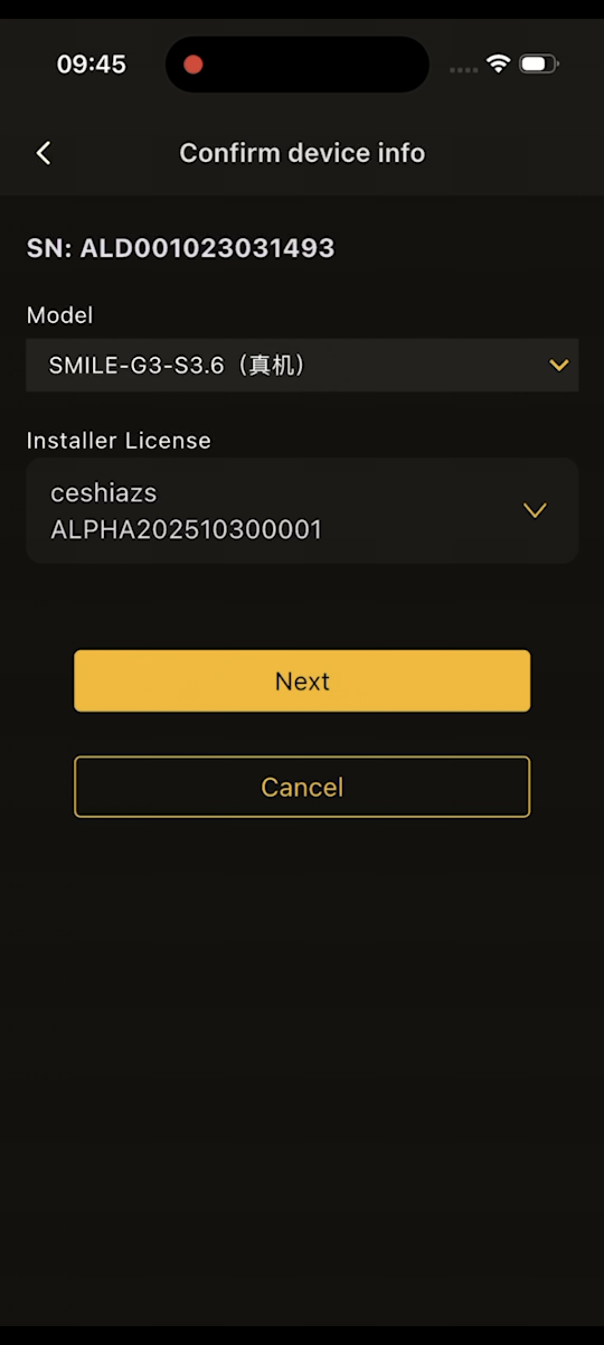
Figure 8-13 Step 3: Enter the device SN and check code, and confirm the device information
Step 4:Wait for the phone to connect to the device.
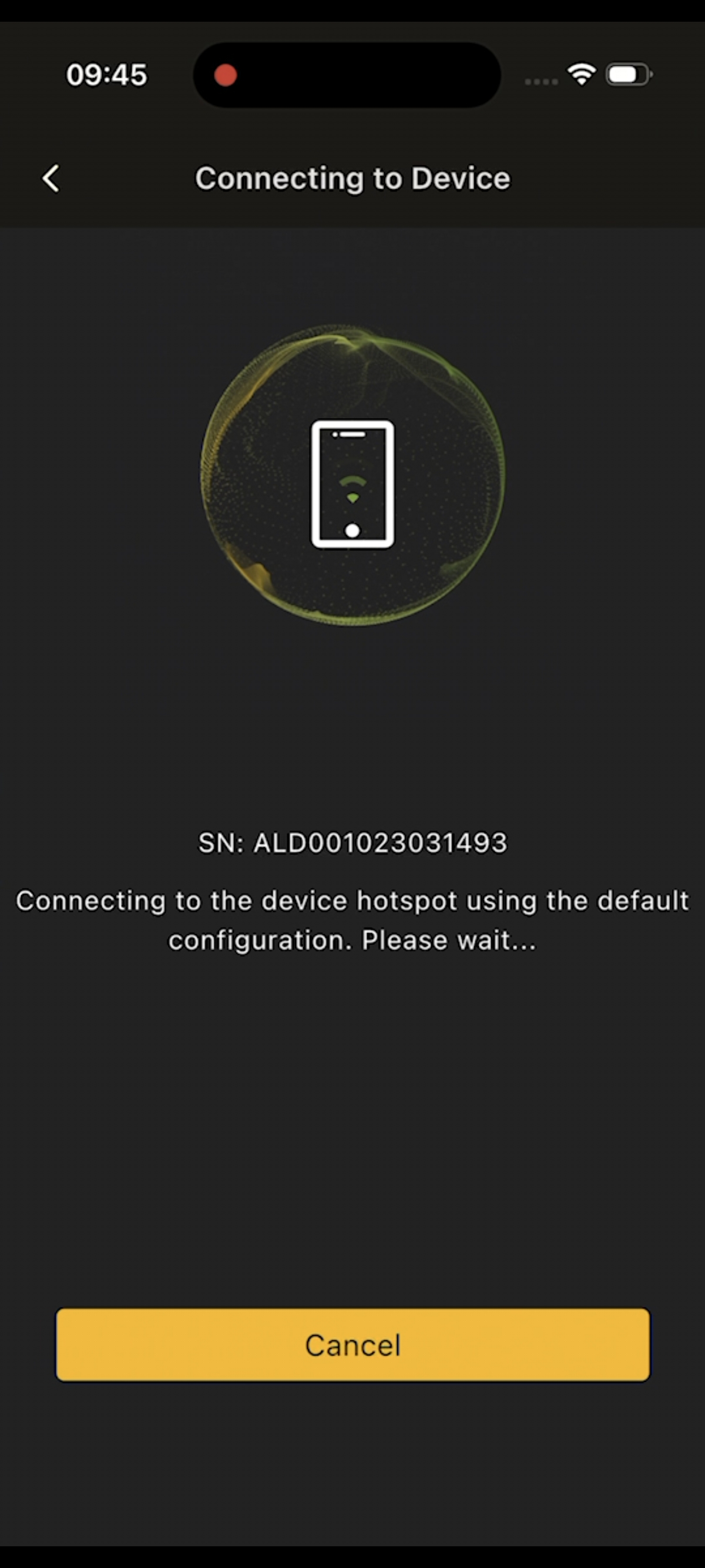
Figure 8-14 Step 4: Wait for the phone to connect to the device
Step 5:Once the phone has successfully connected to the device, select the home Wi-Fi the device needs to connect to and enter the correct password.
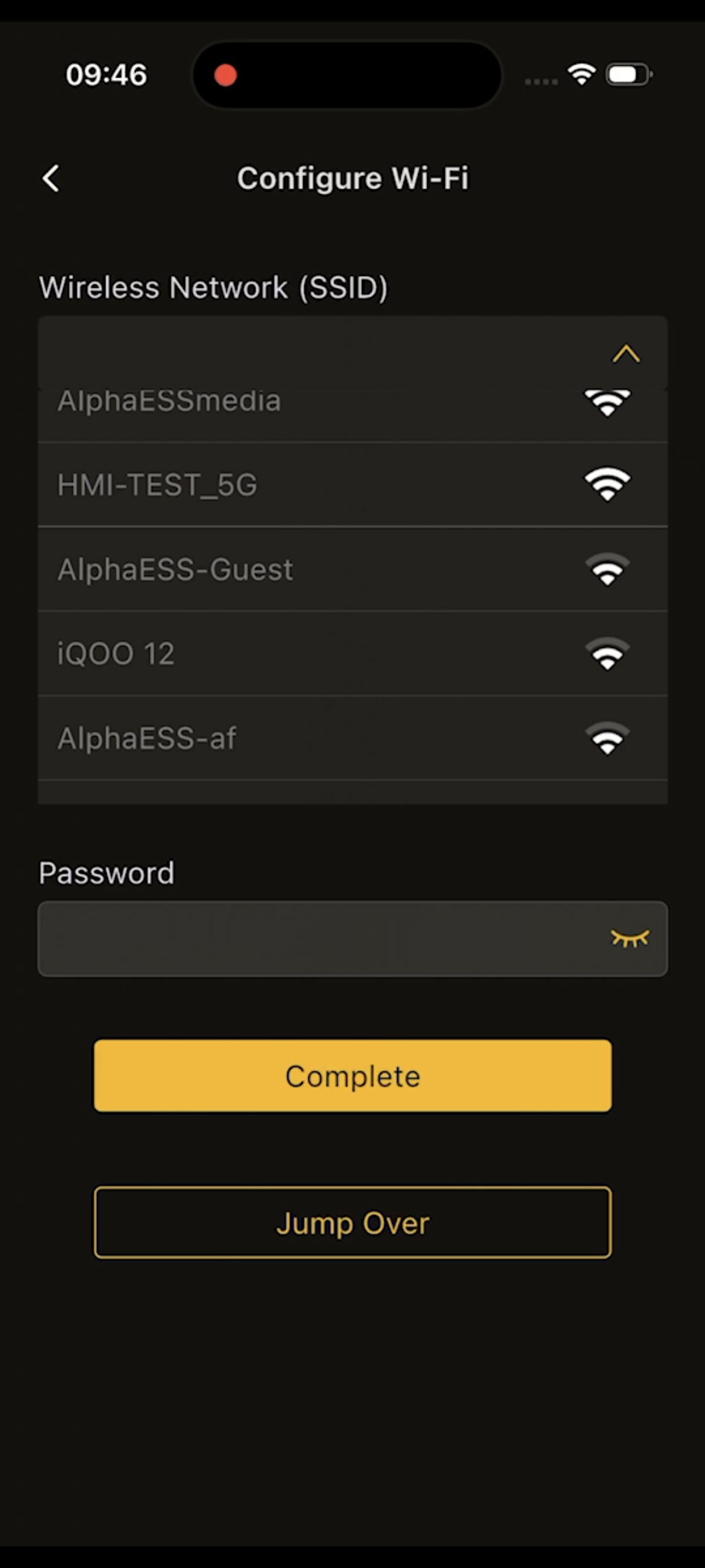
Figure 8-15 Step 5: Select the home Wi-Fi and enter the password
Step 6:Wait for the device to connect to the network and the cloud.
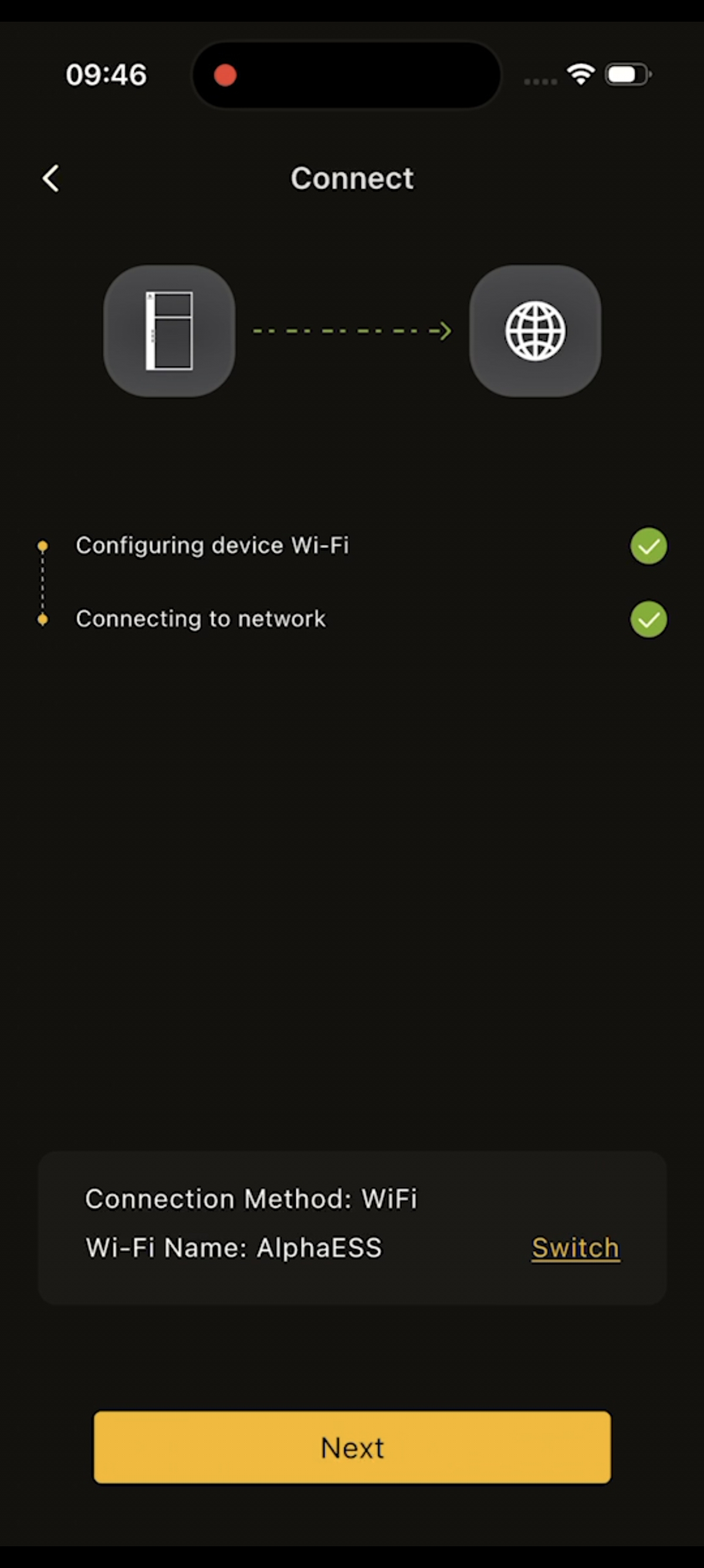
Figure 8-16 Step 6: Wait for the device to connect to the network and the cloud
Basic Information Entry And Device Parameter Configuration
Basic Information Entry
Step 1:Enter the "Install System" screen, select "Basic Information" first to access the basic information form.
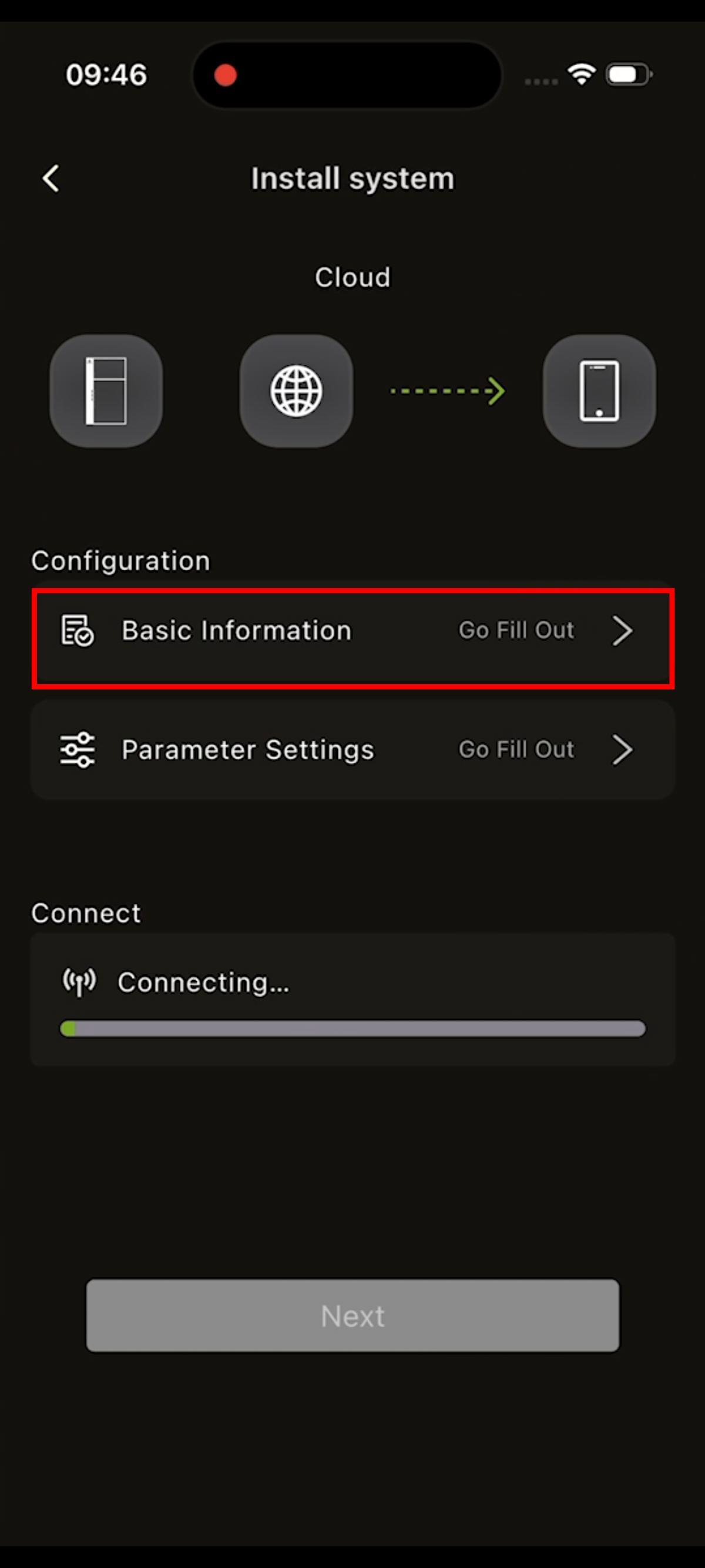
Figure 8-17 Step 1: Open the "Install System - Basic Information" screen
Step 2:Automatically locate or manually enter the device installation address.
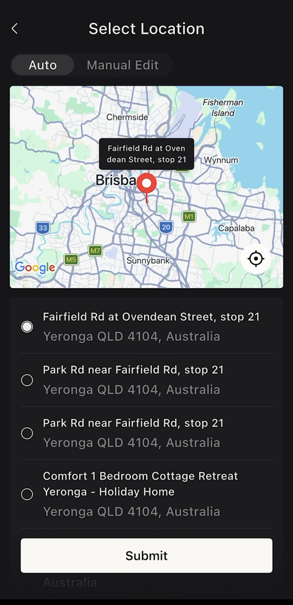
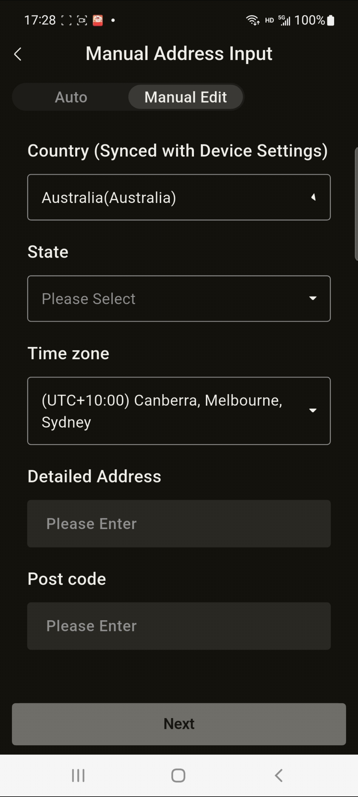
Figure 8-18 Step 2: Automatically locate or manually enter the device installation address
Step 3:Set the device site name and enter the end-user account.Back to "Install System" screen; "Basic Information" marked complete.
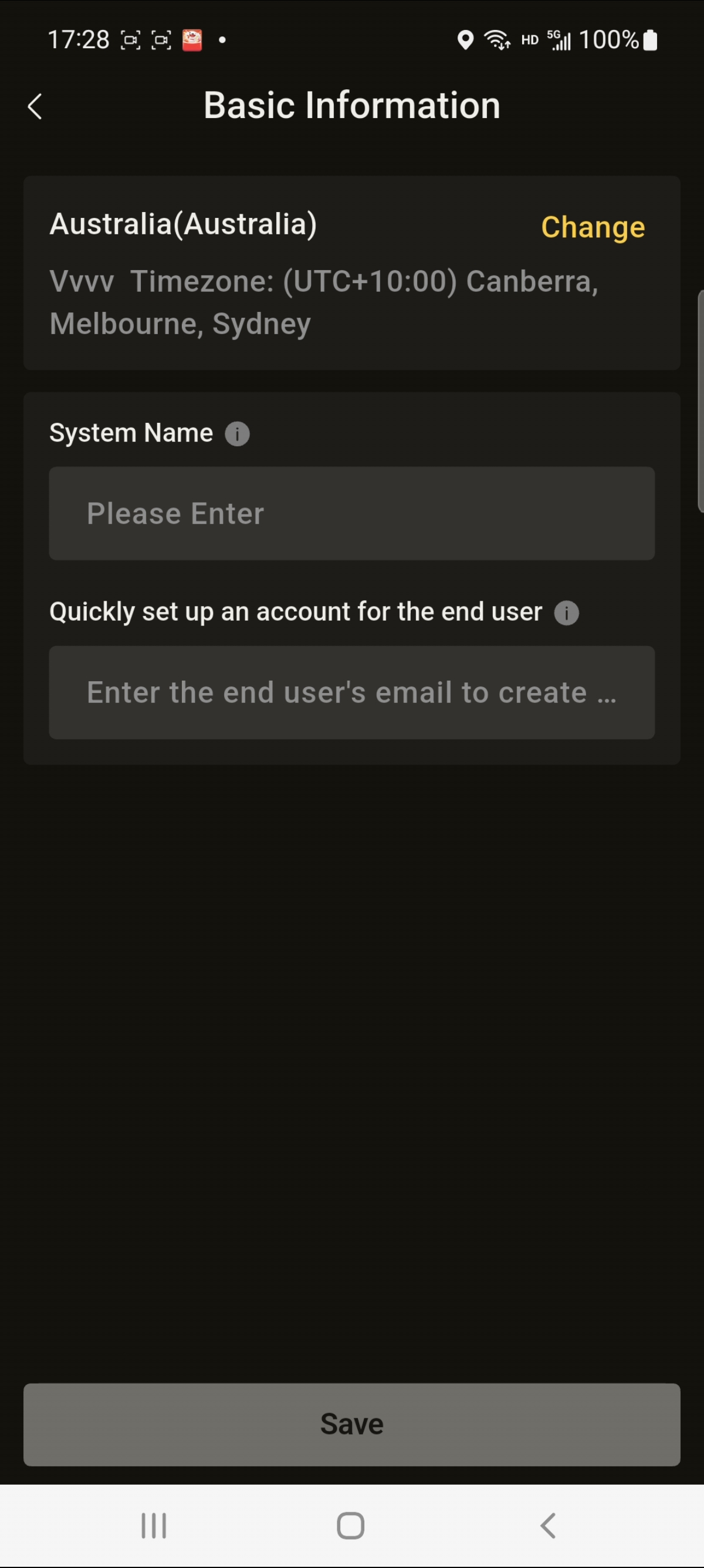
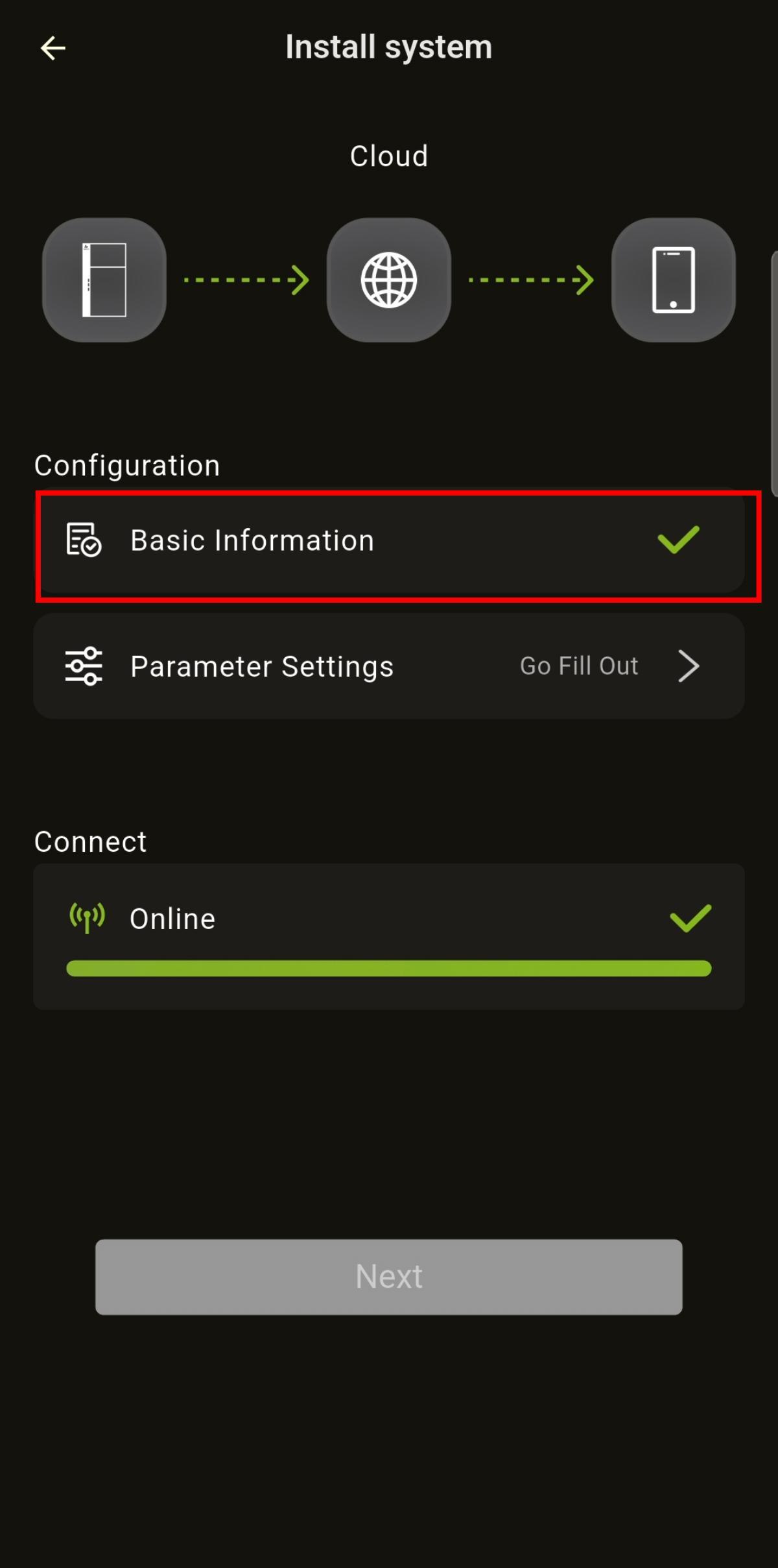
Figure 8-19 Step 3: Set the site name and enter the end-user account
WARNING
- If the automatically located address is found to be inaccurate after verification, you can update the address through the "Change" interface in Step 3.
Device Parameter Configuration
Step 1: Select "Parameter Settings"on the "Install System" screen.
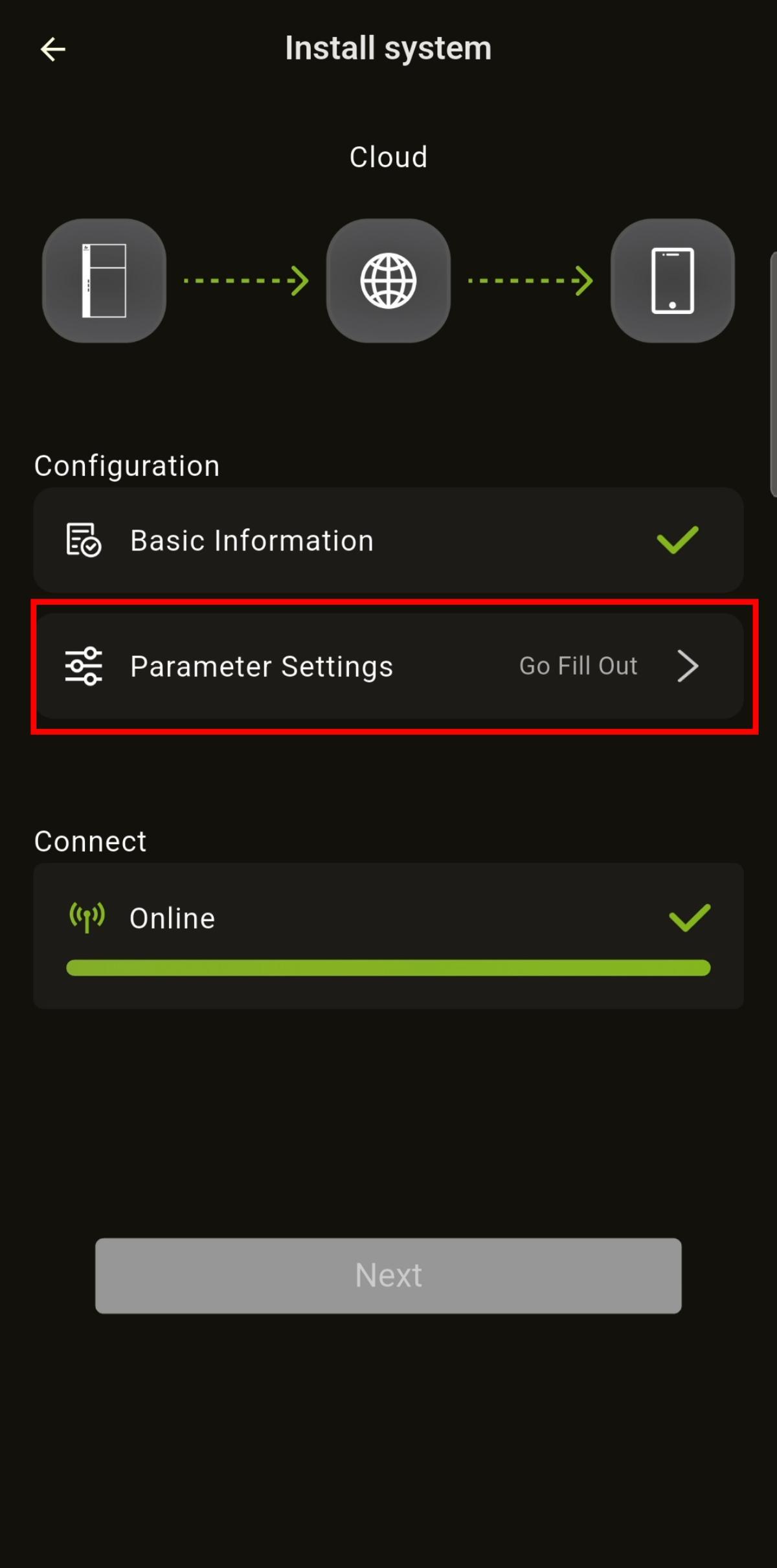
Figure 8-20 Step 1: Select "Parameter Settings" on the "Install System" screen
Step 2:Enter the device installation mode, PV installed capacity, maximum PV feed-in power limit, select the meter type, and other information (For AU, enter region, DNSP, NMI, and other information as required).
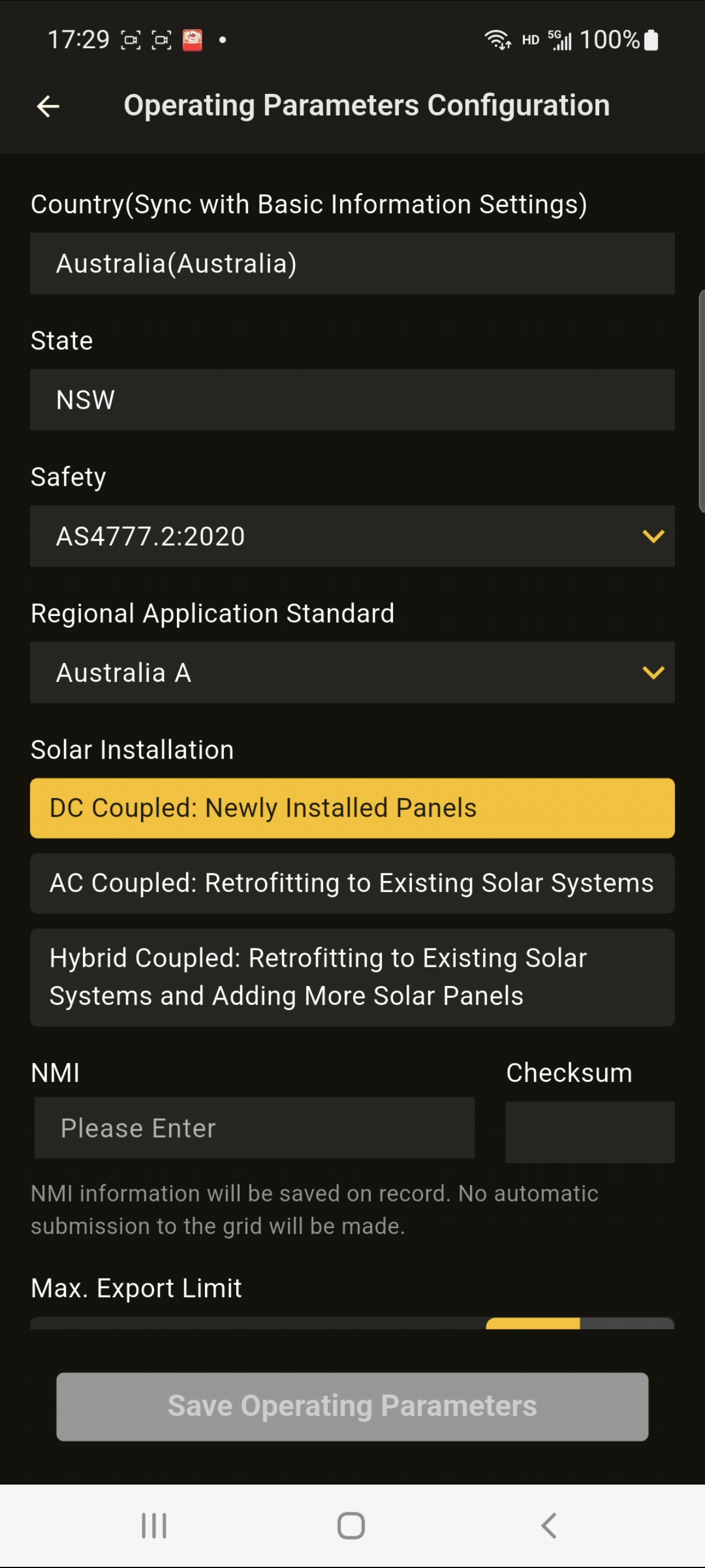
Figure 8-21 Step 2: Configure the device installation mode, PV capacity and meter type
Step 3:Select Device Self-Test / Skip (only some models support self-test).
Models that support self-test: SMILE-G3 Series, SMILE-M Series.
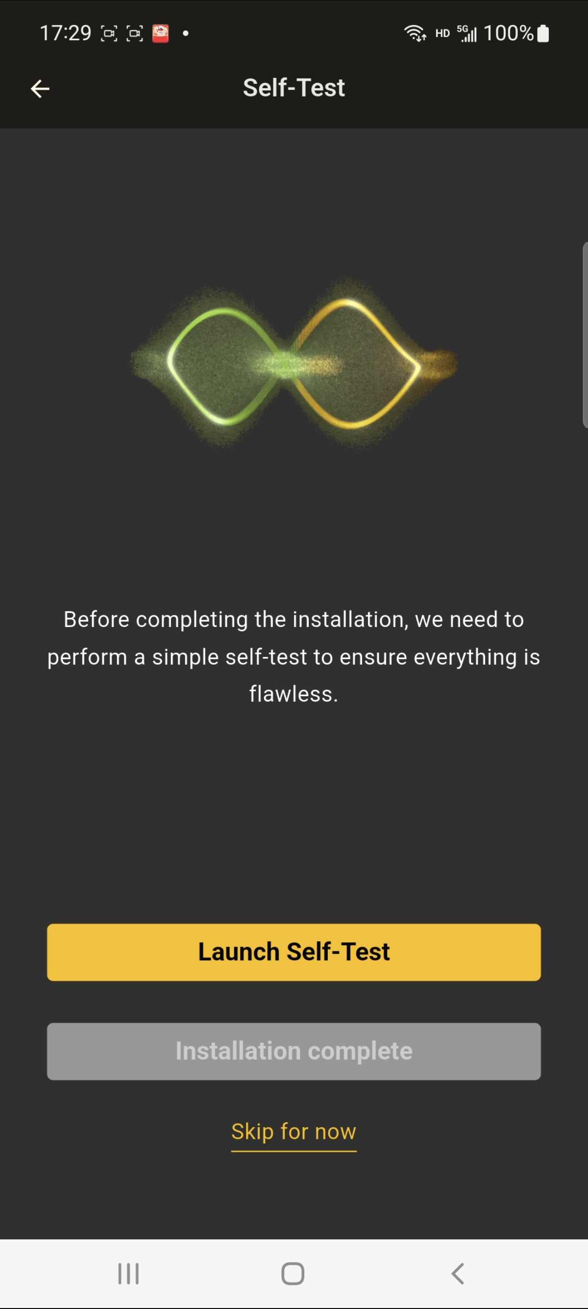
Figure 8-22 Step 3: Select the device self-test
Step 4:Enter the self-test screen and wait for completion. If issues arise, perform detailed checks via Troubleshoot, then re-run the self-test. Self-test completes when no issues are found.
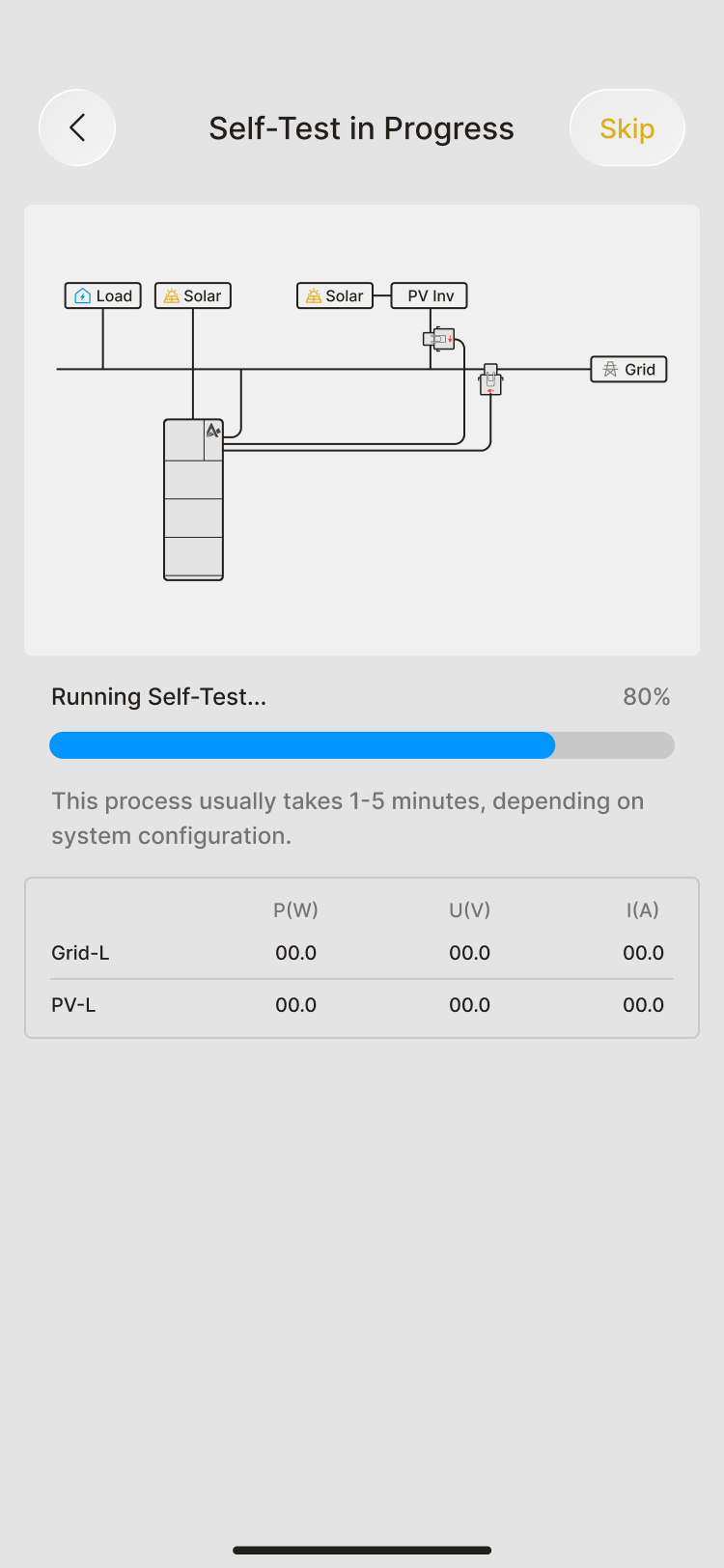
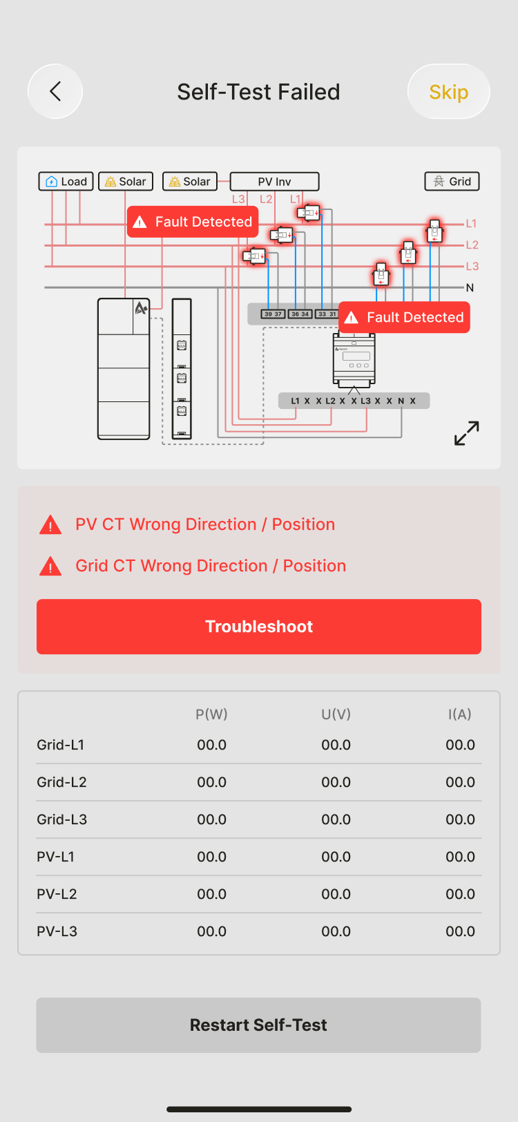
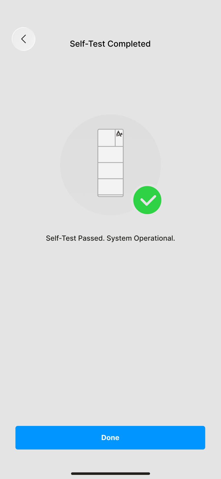
Figure 8-23 Step 4: Self-test in progress, failed and completed screens
Site And System Overview
After installing and commissioning the equipment, check the operating status daily on the Site / System Overview. Log in and select the Workspace to enter.
Site / System List
Enter Site / System List, you can search by Site Name / SNsearch.Click the target site to enter the overview.
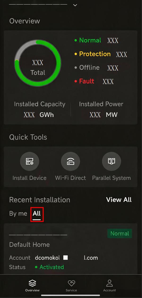
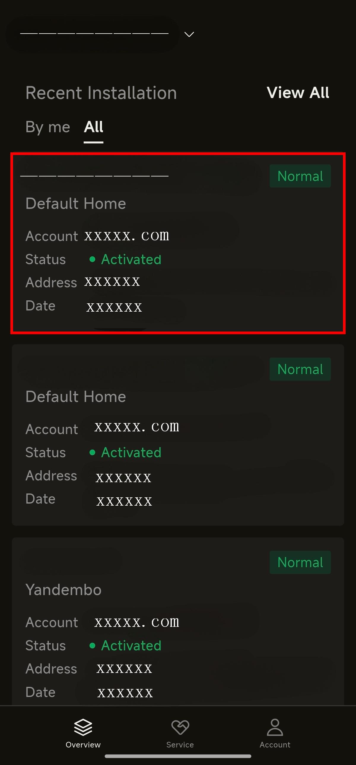
Figure 8-24 Site/System list with search by site name or SN
Overview Energy Flow Overview
Top Status Indicator:
| Status |
|---|
| Normal(All online) |
| Offline(All offline) |
| Protection(Protection Status ) |
| Fault(Fault present) |
When offline, you can click into the "Offline Devices" list.
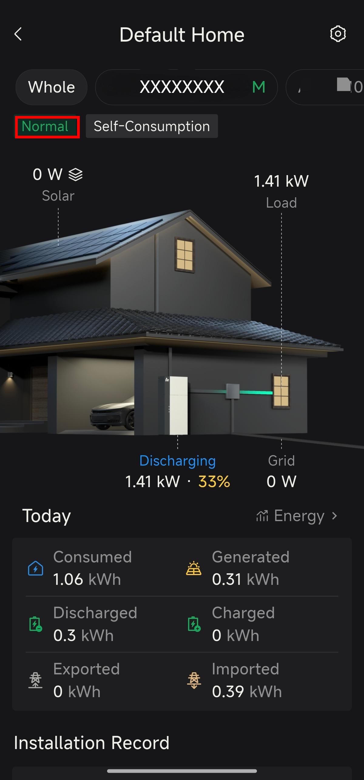
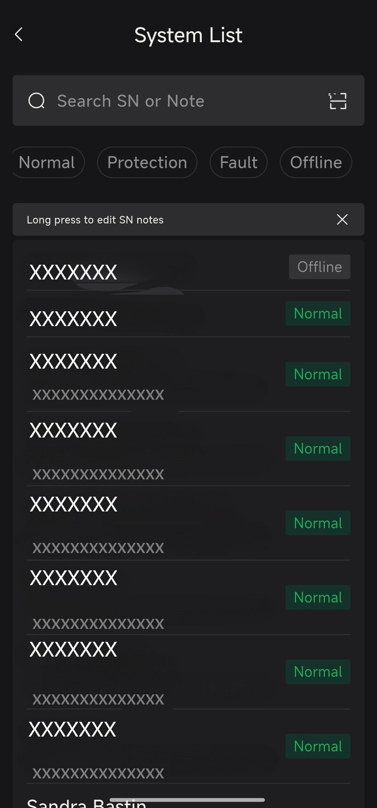
Figure 8-25 Top status indicator and the system list
Middle Energy Flow Visualisation: Real-time display of the power flow directions between PV, the grid, Load, Battery (and EV chargers, etc.) power flow direction and current power values.
Click the top right to view and configure the site operating mode, tariff information, VPP scheduling and individual devices.
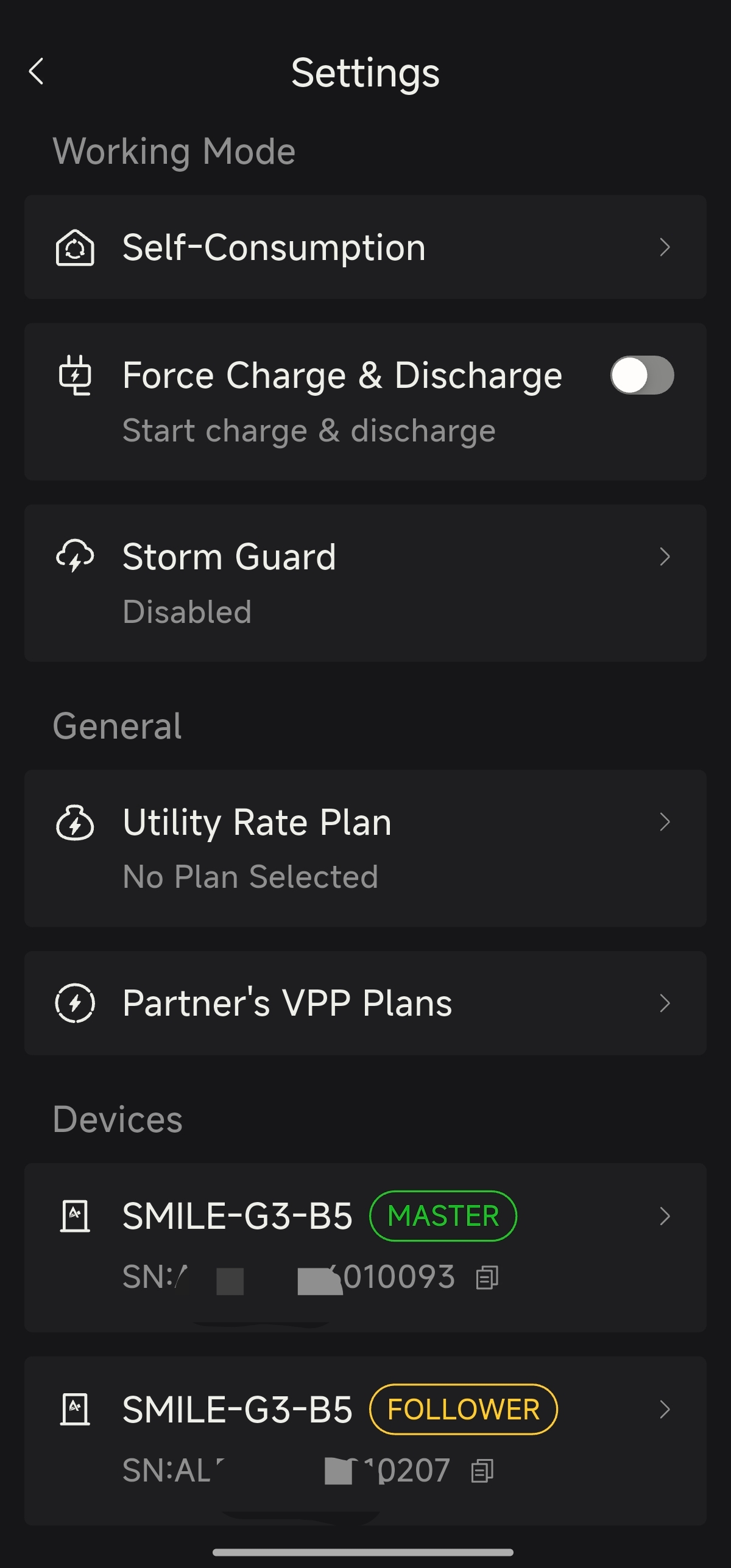
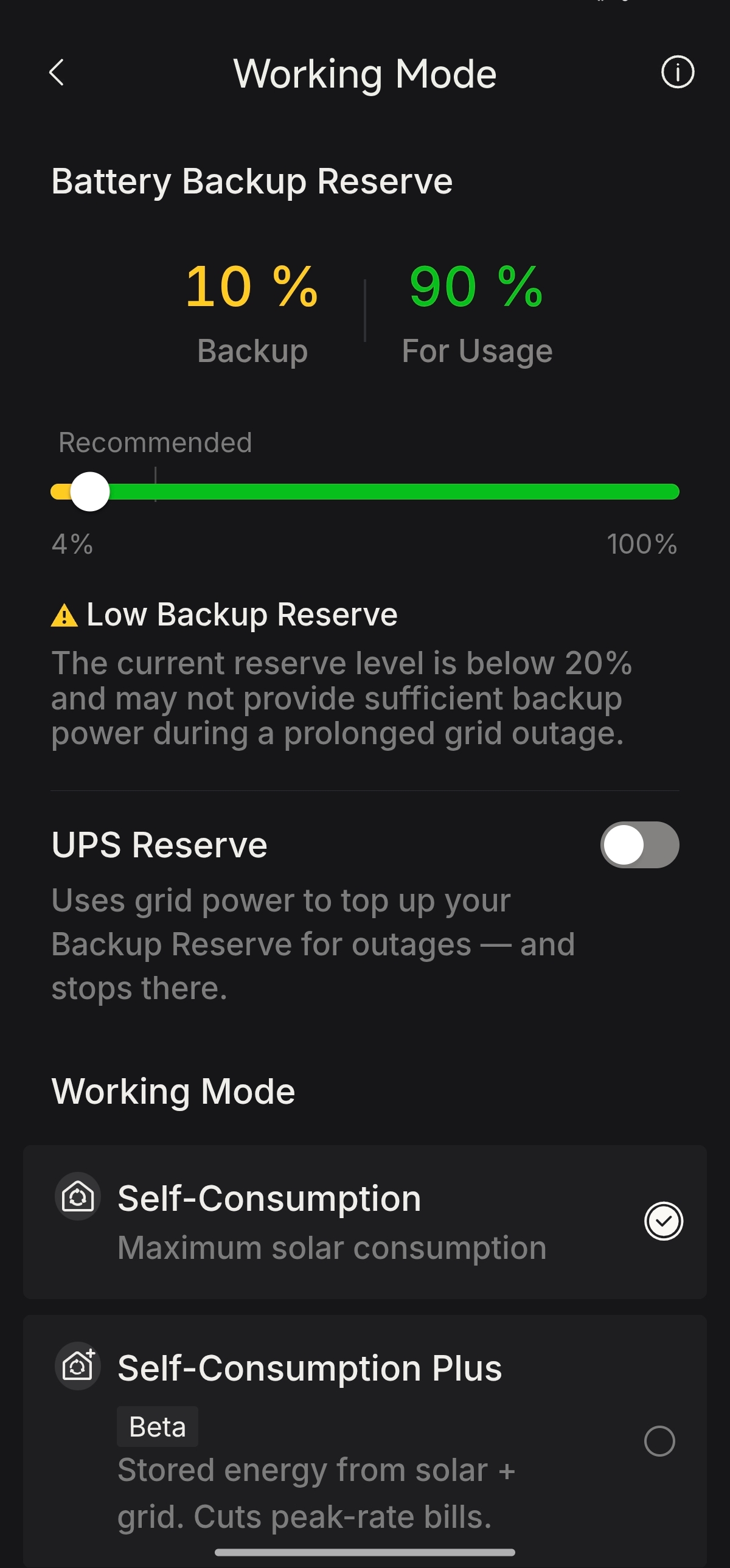
Figure 8-26 Site operating mode and configuration entries
Energy Charts and Data
Switch Daily / Monthly / Yearly dimensions to view electricity consumption trends and the balance between generation & consumption.
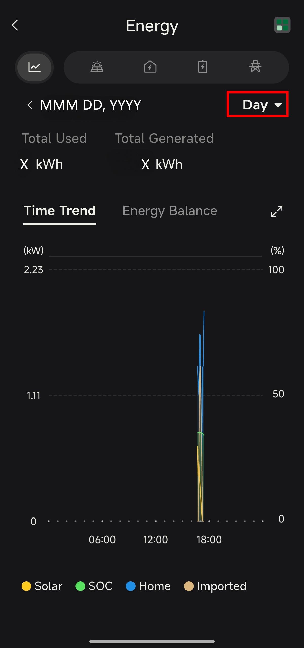
Figure 8-27 Daily/monthly/yearly energy consumption and generation trends
Switch the daily/monthly/yearly energy data corresponding to each metric such as installed PV, Home Load, Battery, grid, etc.
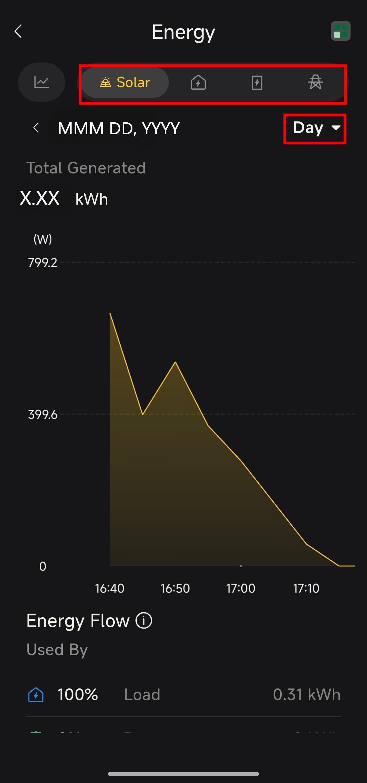
Figure 8-28 Energy data of each metric (PV, Home Load, Battery, grid, etc.)
View the site's renewable energy achievement data.
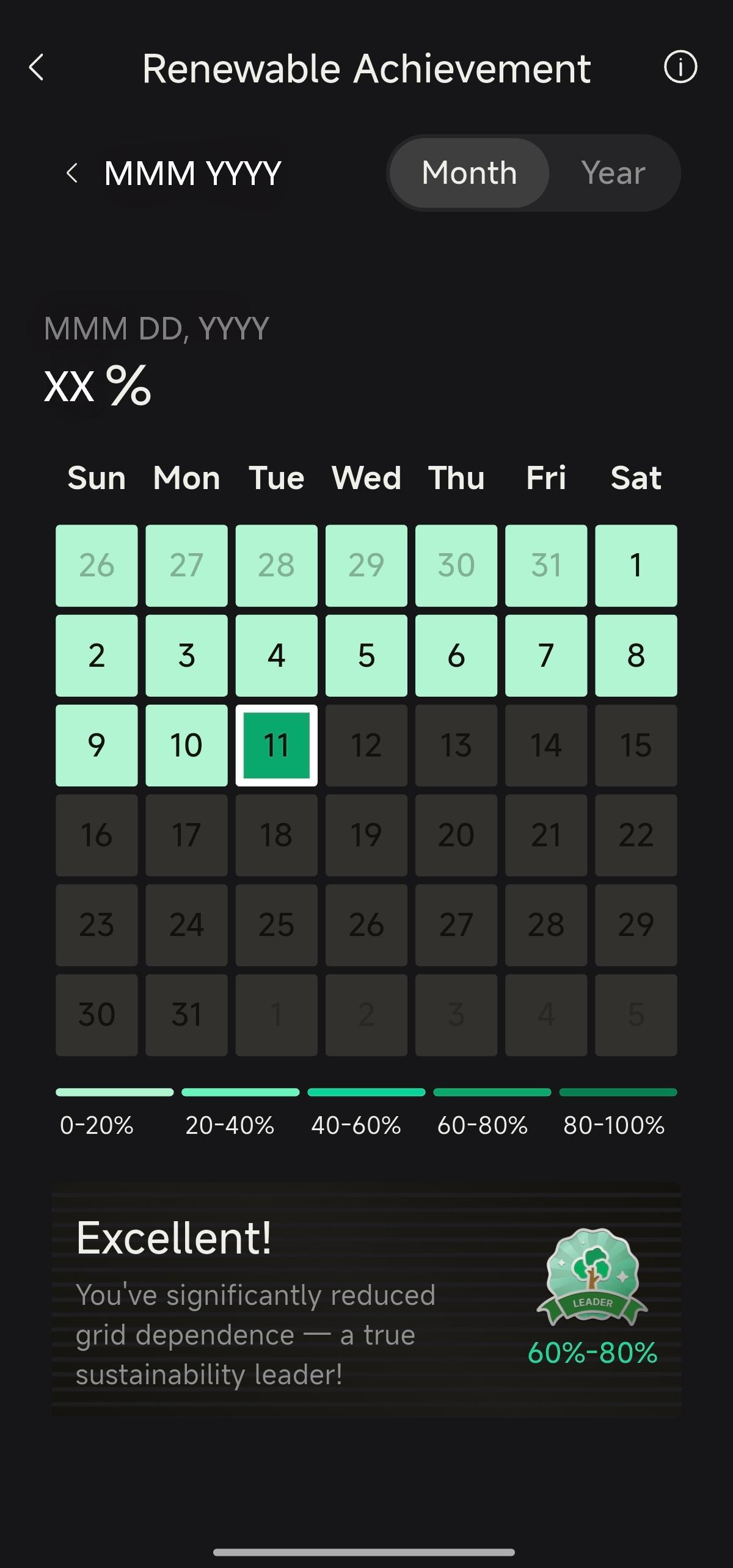
Figure 8-29 Renewable energy achievement data
Parallel Installation
Parallel Installation
Step 1:Carry out the standalone installation in sequence (see Chapter 4: Wi-Fi Network Configuration and Commissioning for standalone installation).
Step 2:Select "Parallel System" in Quick Tools, click "Add Parallel" at the bottom, then distinguish Master/Slave SN and Check Code as prompted.
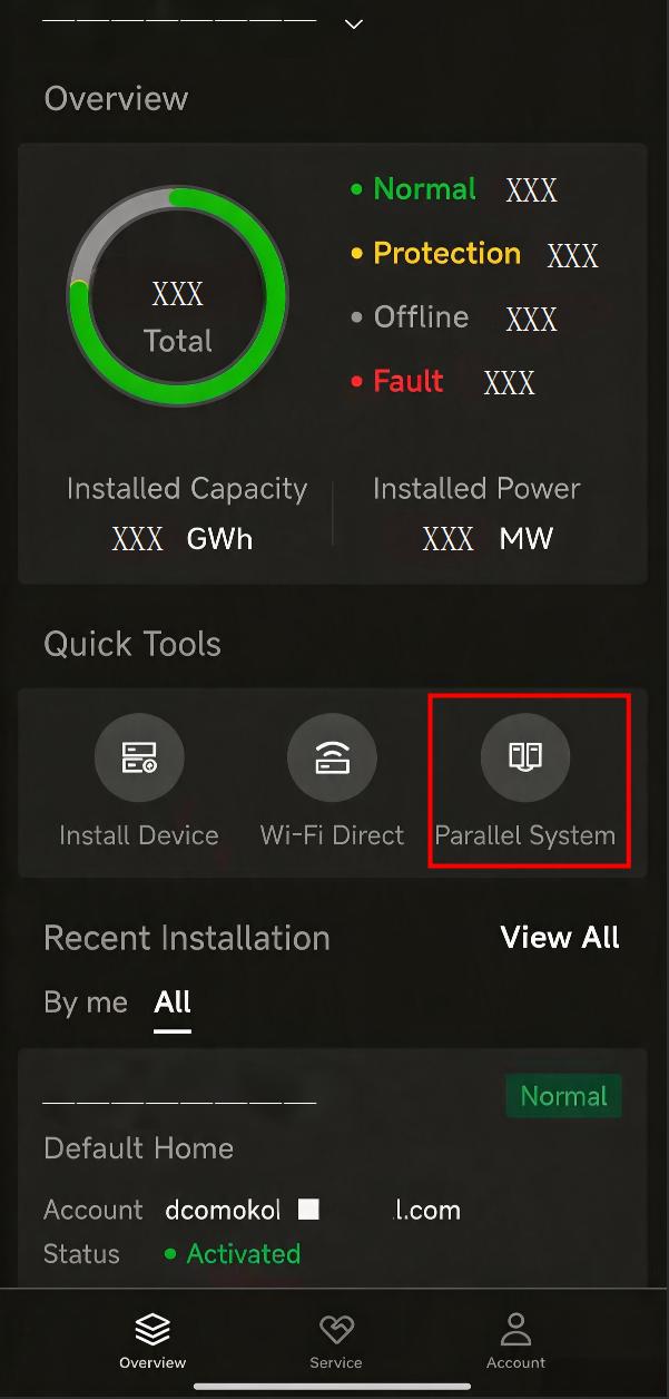
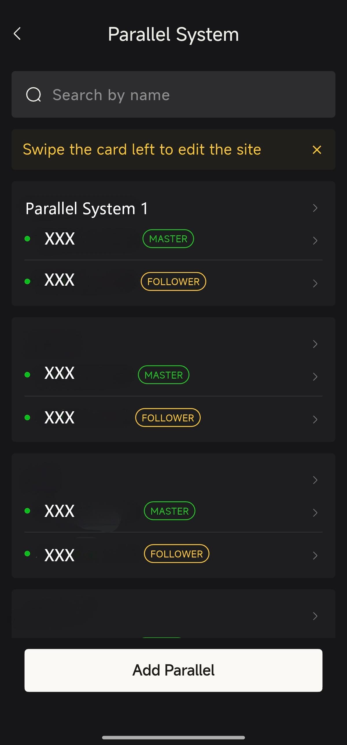
Figure 8-30 Step 2: Enter the "Parallel System" page and add the Master/Slave devices
Step 3:Submit the parallel operation information; once the system has completed the software update, the parallel installation is complete.
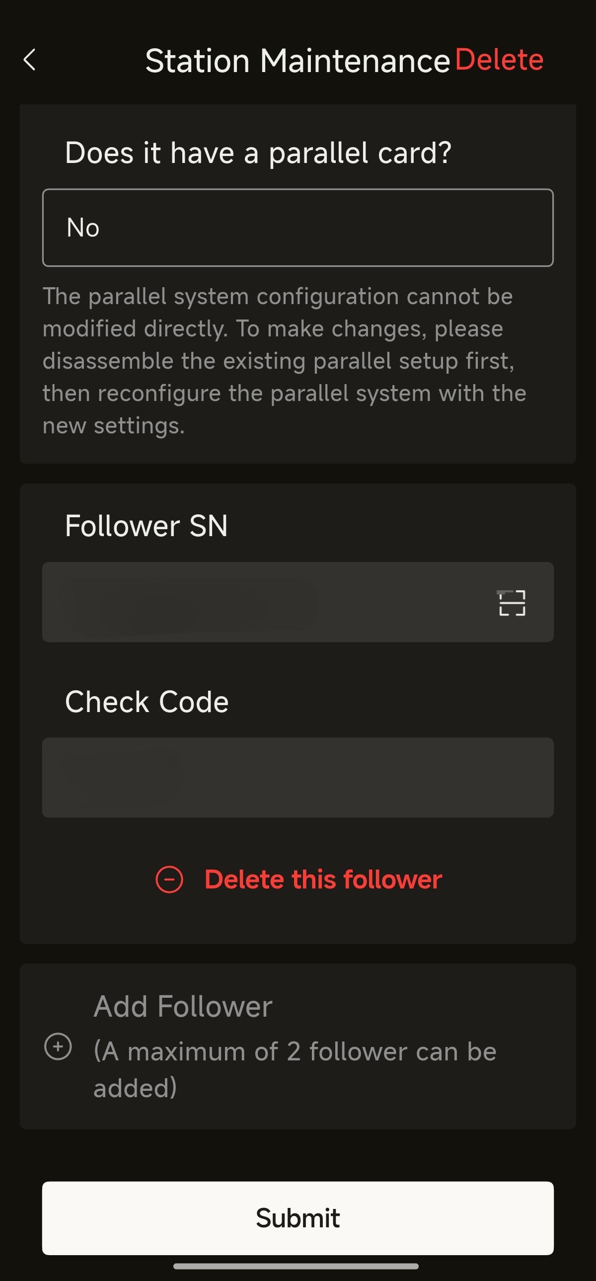
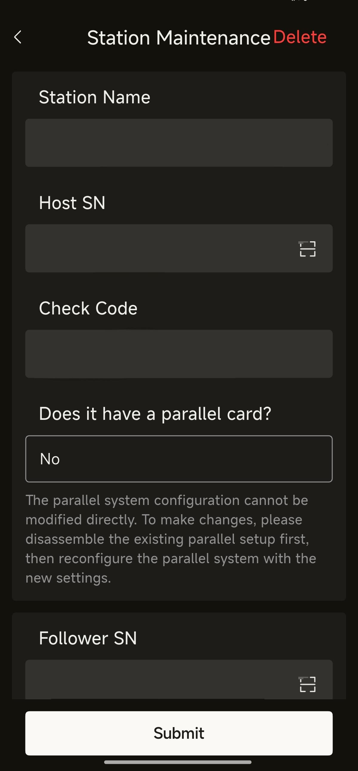
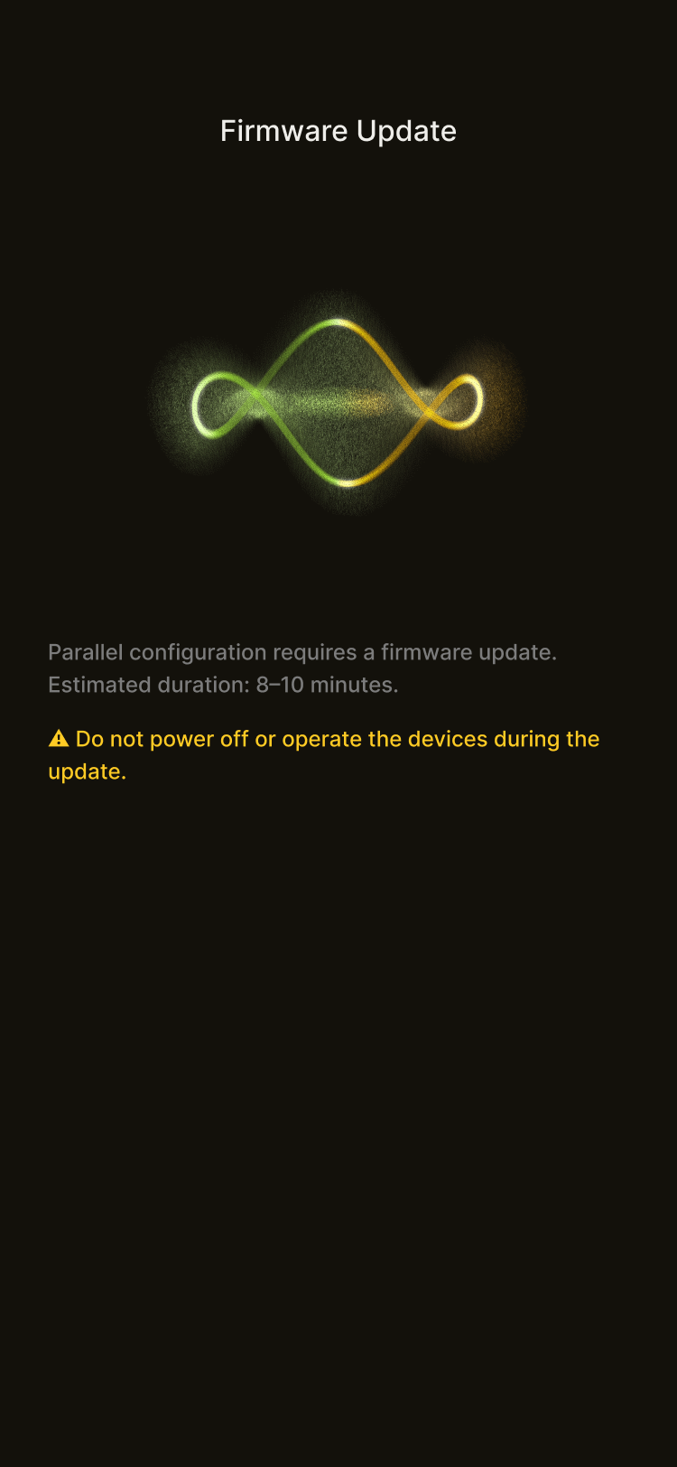
Figure 8-31 Step 3: Submit the parallel system information and wait for the firmware update
WARNING
- If you are installing a G3-S5/B5 series model, please confirm whether the device is equipped with a parallel card. If so, select the "Yes" option in the "Does it have a parallel card?" field.
Parallel System Management
Step 1:On the home page, select Quick Tools Parallel System.
Figure 8-32 Step 1: Select "Quick Tools - Parallel System" on the home page
Step 2:View the parallel system list, and select the parallel site to enter.
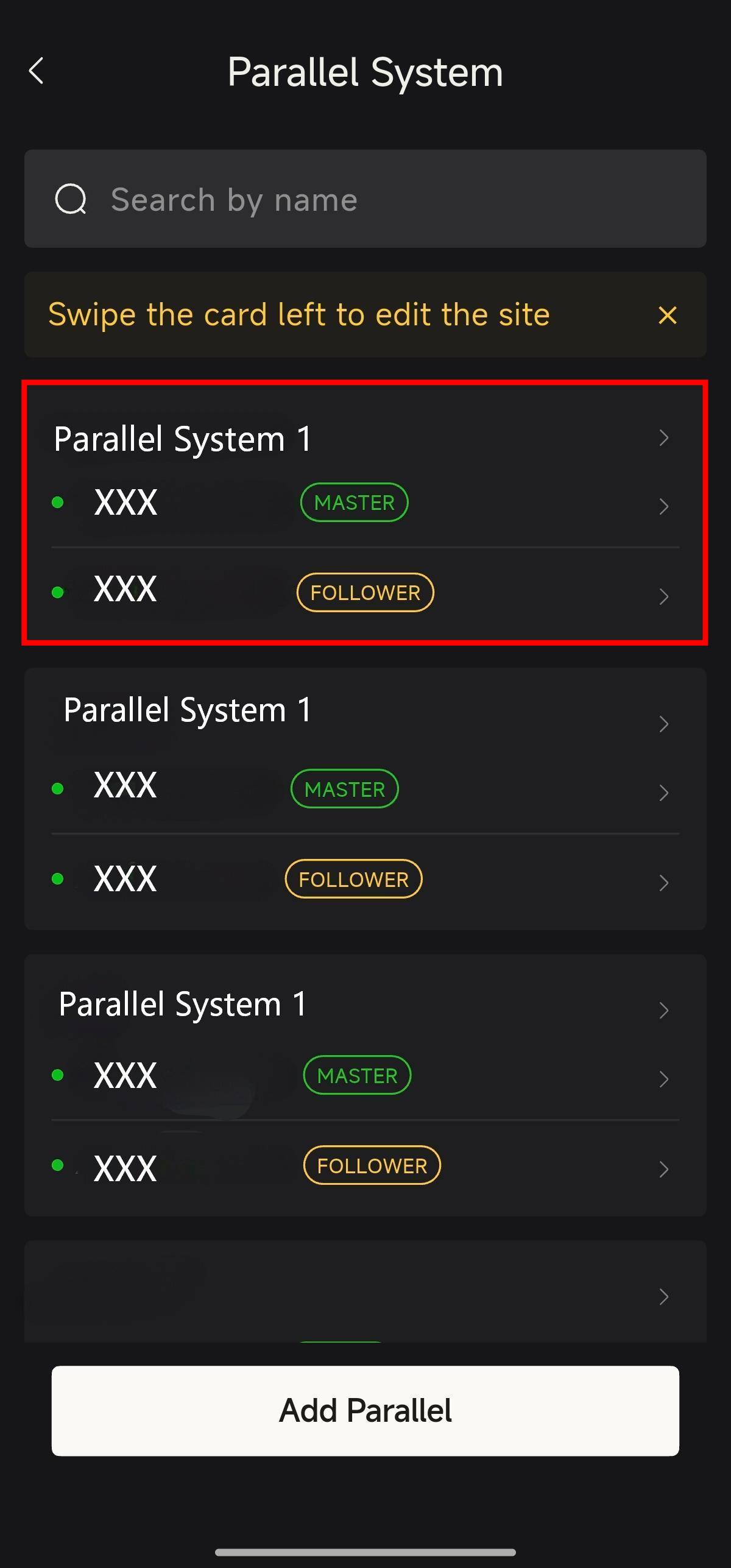
Figure 8-33 Step 2: View the parallel system list and select the parallel site
Step 3:View the overall operating information of the parallel site, and switch to the standalone view at the top.
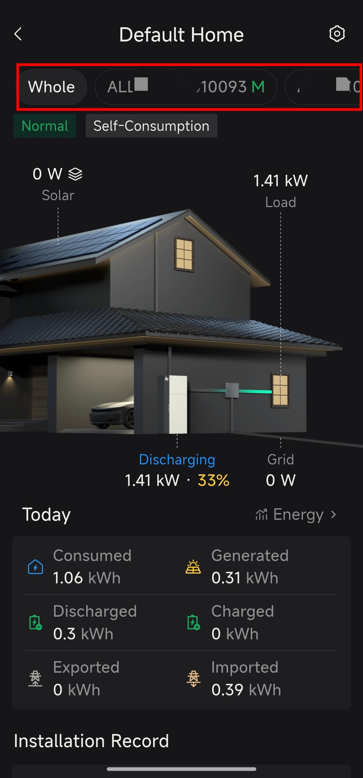
Figure 8-34 Step 3: View the overall operating information of the parallel site
Parallel Removal
Step 1:In the parallel system list, after selecting the site to be removed, swipe left to edit.
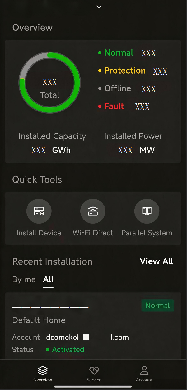
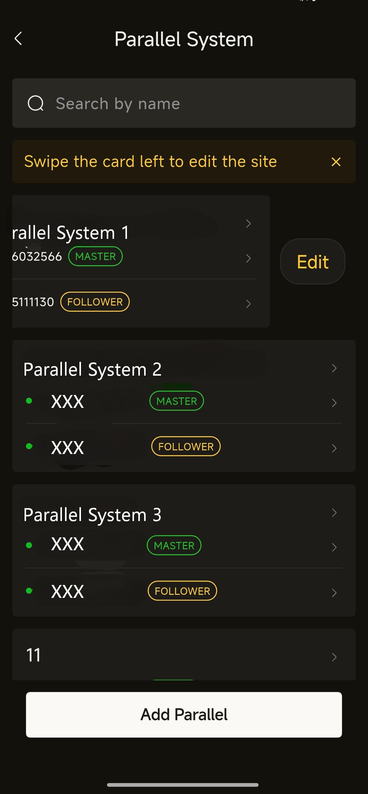
Figure 8-35 Step 1: Select the parallel site to be removed and swipe left to edit
Step 2:In the edit details, click delete to remove the parallel site.
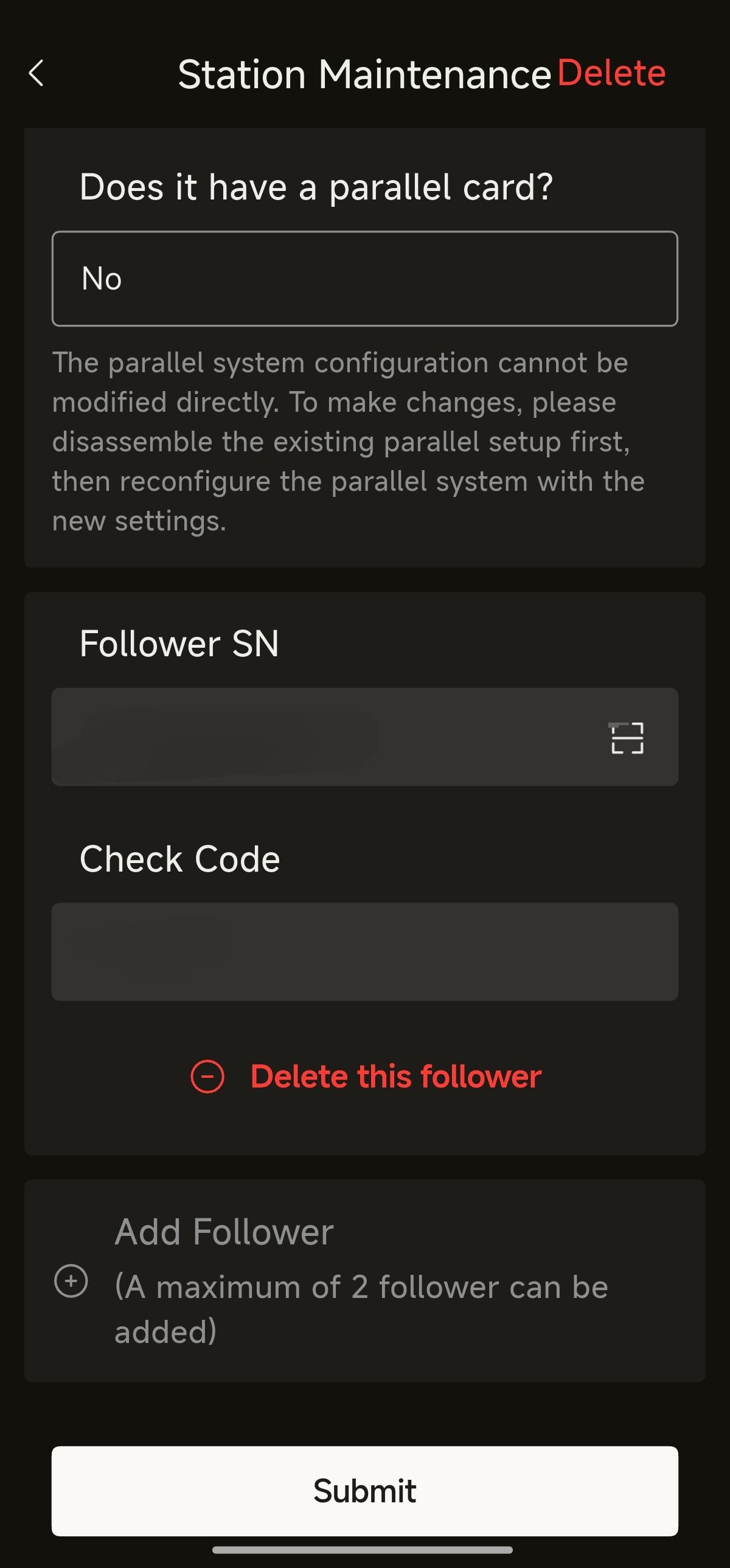
Figure 8-36 Step 2: Click "Delete" in the edit details to remove the parallel site
WARNING
- Parallel Removal ≠ Device Removed from Site: After the parallel relationship is removed, the Device remains at the original site.
- Removed from Site Yes an independent second step operation, and must be carried out separately.
- When deleting the parallel configuration, remove the parallel wiring harness physically at the same time to avoid inaccurate single-unit data.
Register on AlphaCloud
Register an Installer Account on AlphaCloud
If you do not already have an Installer account, you can create a new account on our web server for system monitoring purposes. In addition, Alpha Warranty is predicated on this connection to our web server.
The data produced prior to registration can be synchronized to the web server.
Step 1: Please open the portal: www.alphaess.com.
Step 2: Please fill in “Username”, “Password” and click “Login” if you have already
registered.
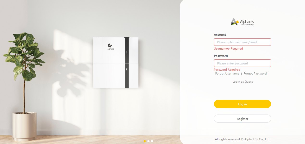
Figure 8-37 Alpha Cloud platform login page
If not, please register by filling in the following web form.
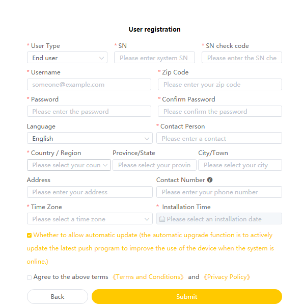
Figure 8-38 User registration
In this form, all fields with a red star are required.
*Serial Number: SN (please see the type label of the inverter)
*Username: 5-15 letters / numbers
*Password: 5-15 letters / numbers / characters
More details are available in the Online Monitoring Web Server Installers User Manual, which can be downloaded from the AlphaESS homepage.
Install New System on AlphaCloud
Installers who haven't yet registered need to click “Register” to visit the registration page. Please refer to the “AlphaCloud Online Monitoring Web Server Installers User Manual”, which you can get from the Alpha sales team and get a Alpha Installer license number.
Log in to your installer account and choose Storage System Maintenance "Install New System" to register a new
system.
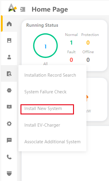
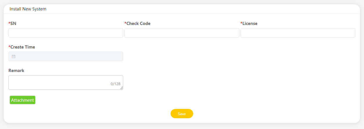
Figure 8-39 Install the new system on the Alpha Cloud platform
Enter the system S/N, check the code, license, and installation date, then click the “Save” button. The red * indicated a required field. Click the “Browse” button to select any attachment you want to add.
Check System Wiring and Meter Installation
Check the grid's voltage range and frequency range and the installation (including location, direction and phase sequence) of all CT(s) and/or meter(s).
You can commission the system after the system configuration process.
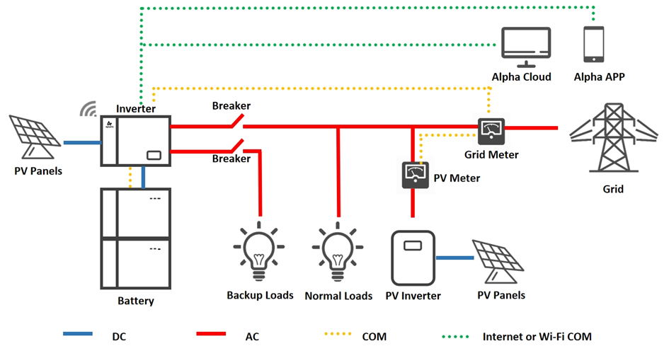
Figure 8-40 Brief wiring diagram of hybrid system
Detailed operating steps to check system wiring and meter installation as follows:
Please perform the steps below for the circuit breakers and PV switch in the system.
Switch on the battery circuit breaker of the energy storage inverter.
Switch on the battery circuit breakers of all batteries.
Switch on the AC circuit breaker between the grid port of the energy storage inverter and the grid.
Switch on the AC circuit breaker between the backup port of the energy storage inverter and the loads.
Switch off the PV switch of the energy storage inverter (if there is any).
Switch off the AC circuit breaker (if there is any) between the PV inverter and the grid.
At this moment, the energy storage inverter will enter NORMAL state.
Please turn off all loads. If you can’t, please ensure that there aren't loads of large power fluctuations connected in the system.
Log on to the App and click to page “My System” and note the current "Load".
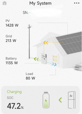
Figure 8-41 My system page on the APP
- Operate the App and follow the instructions below to enable “Charge Batteries from the Grid”.
②
⑤
Please adjust the
SOC to 100.
③
④
①
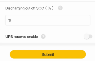
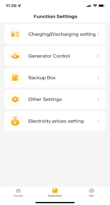
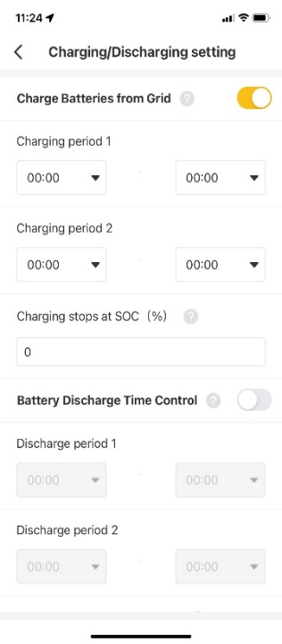
Click “Submit” when the settings are completed.
Figure 8-42 Settings for charging the battery from the power grid
If the formula “Grid Power**≈ Load** + Battery Charging Power” fits well, the grid meter installation of the energy storage inverter is correct. Please remember to deactivate the “Charge Batteries from Grid” by clicking “OFF” and save the changes.
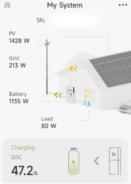
Figure 8-43 Confirmation of installation of power grid electricity meters
If the formula above does not apply, please perform the troubleshooting below.
Meter Type | Solution |
BB, BB Plus | Please refer to the relative system wiring diagram to check the wiring. If the error persists, contact AlphaESS customer service for further check. |
Meter (without CT) | Check the wiring and location of the grid meter. |
Meter (with CT) | Check the location, direction, phase sequence and cable connection of the grid CT. |
CT Only | Check the location, direction and cable connection of the grid CT. |
P1 meter reader | Check the connection and installation configuration of the P1 meter reader. |
- If there is no PV inverter in the system, please skip this step.
If a PV inverter exists in the system, switch on the AC breaker between the PV inverter and the grid.
In the AlphaESS App, turn to “Running Information” and check the power value of “PV Inverter Power”. If the power value is positive, the meter installation of the PV inverter is correct.
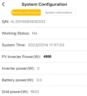
Figure 8-44 Check the power of the photovoltaic inverter
If the power value of “PV Inverter Power” is negative, please perform the troubleshooting below.
Meter Type | Solution |
BB, BB Plus | Please refer to the relative system wiring diagram to check the wiring. If the error persists, contact AlphaESS customer service for further check. |
Meter (without CT) | Check the wiring and location of the grid meter. |
Meter (with CT) | Check the location, direction, phase sequence and cable connection of the grid CT. |
CT Only | Check the location, direction and cable connection of the grid CT. |
P1 meter reader | Check the connection and installation configuration of the P1 meter reader. |
If there are PV modules connected directly to the energy storage inverter, switch on the PV switch of the energy storage inverter.
Switch off the AC breaker between the grid port of the energy storage inverter and the grid. At this moment, please check whether the electrical appliance connected to backup side of the energy storage inverter runs normally. Otherwise, please contact Alpha service for further check.
INFO
During commissioning, if the LEDs on the display panel of the inverter or the battery show red or yellow, please refer to the troubleshooting chapter of the Installation, Operation & Maintenance Manual.
- Congratulations! All required checks of system wiring and meter installation have been completed.
Meter Setting
Meter Setting on Alpha Cloud
Step 1:
When the system work mode is selected as “DC”, click the slider under the item “Grid Meter” to turn the “Meter” icon orange.
When the system work mode is selected as “AC” or “Hybrid”, click the sliders under the items “Grid Meter” and “PV side meter” to turn the “Meter” icons orange.
Step 2:
Click "Save" and wait a few minutes to refresh the page.
When the “Meter Model” displays DTSU666 model, the setting is successful.
WARNING
Do not modify the “Meter CT Ratio”.
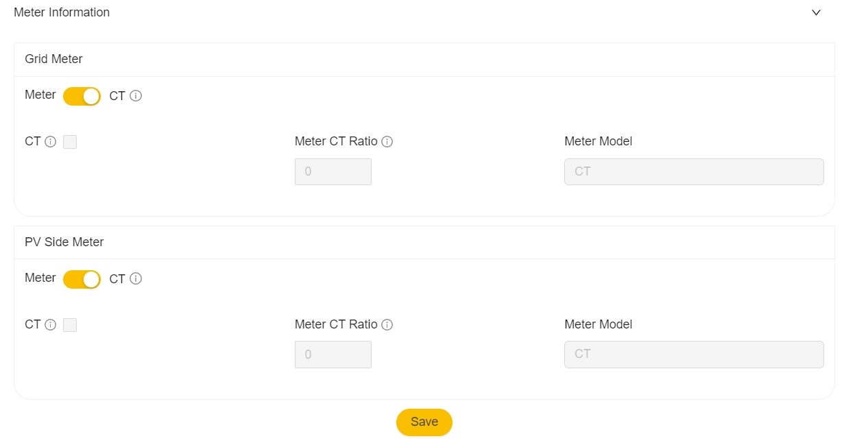
Figure 8‑45 Electricity meter Settings in AlphaCloud
Meter Setting on the AlphaESS App
Step 1:
When the system work mode is selected as “DC”, only tick the "Meter" icon on the right of the “Grid Meter”.
When the system work mode is selected as “AC” or “Hybrid”, tick the two "Meter" icons on the right of the “Grid Meter” and the “PV Meter”.
Step 2:
Click "Submit" and enter the “System information” page to check the meter model. When the “Meter Model” displays DTSU666 model, the setting is successful.
WARNING
Do not modify the “CT” ratio.
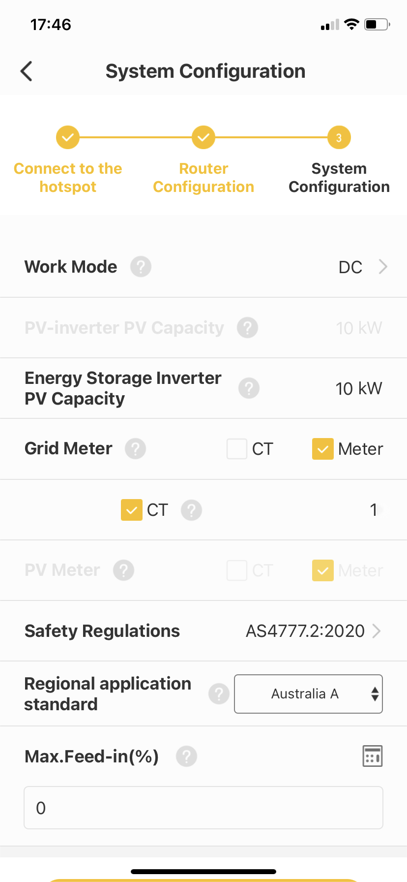
Figure 8‑46 Electricity meter Settings in Alpha ESS App
P1 Meter Setting
Note: Versions 6.4.3 and above of the AlphaESS APP support P1 Meter.
Step 1:
Open the AlphaESS App → Enter the installation system → Check the installation configuration.
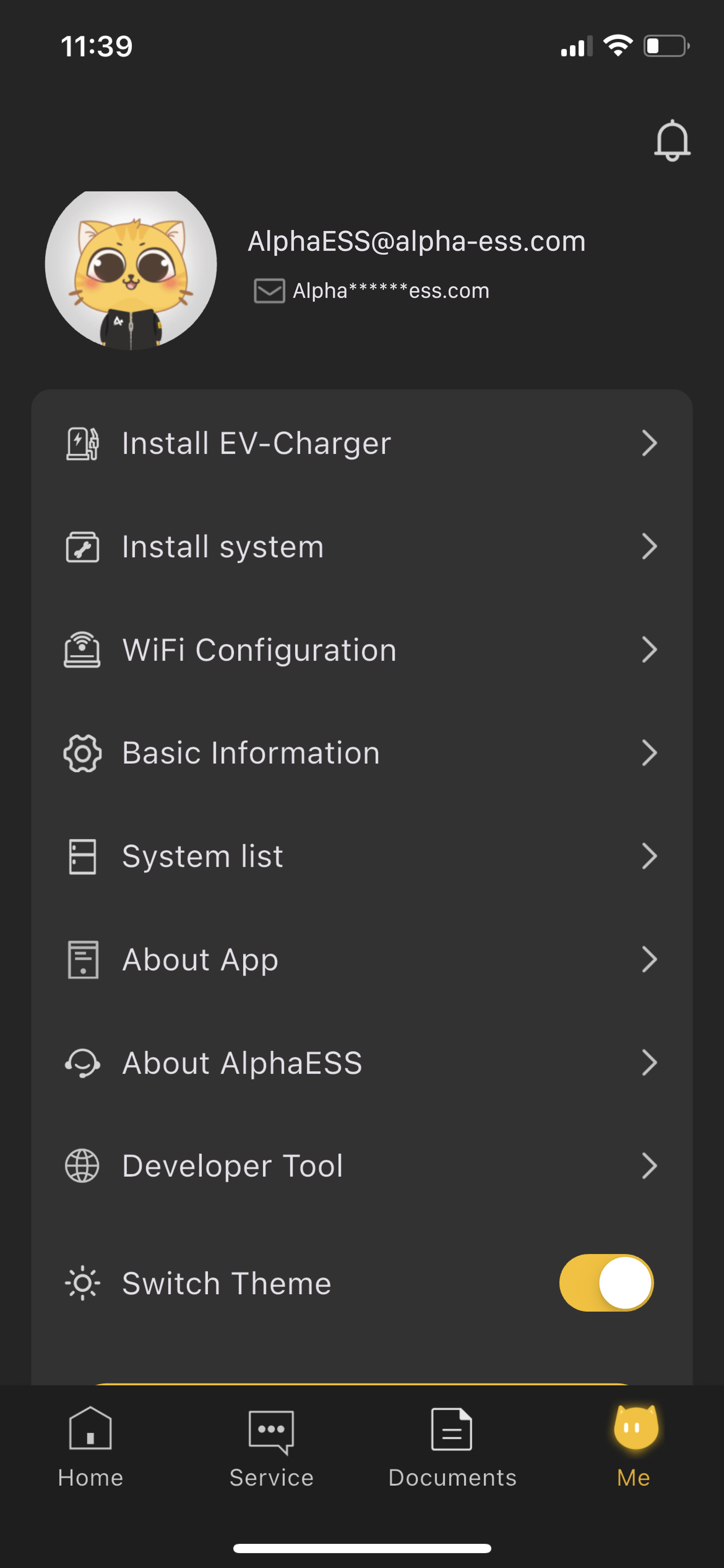
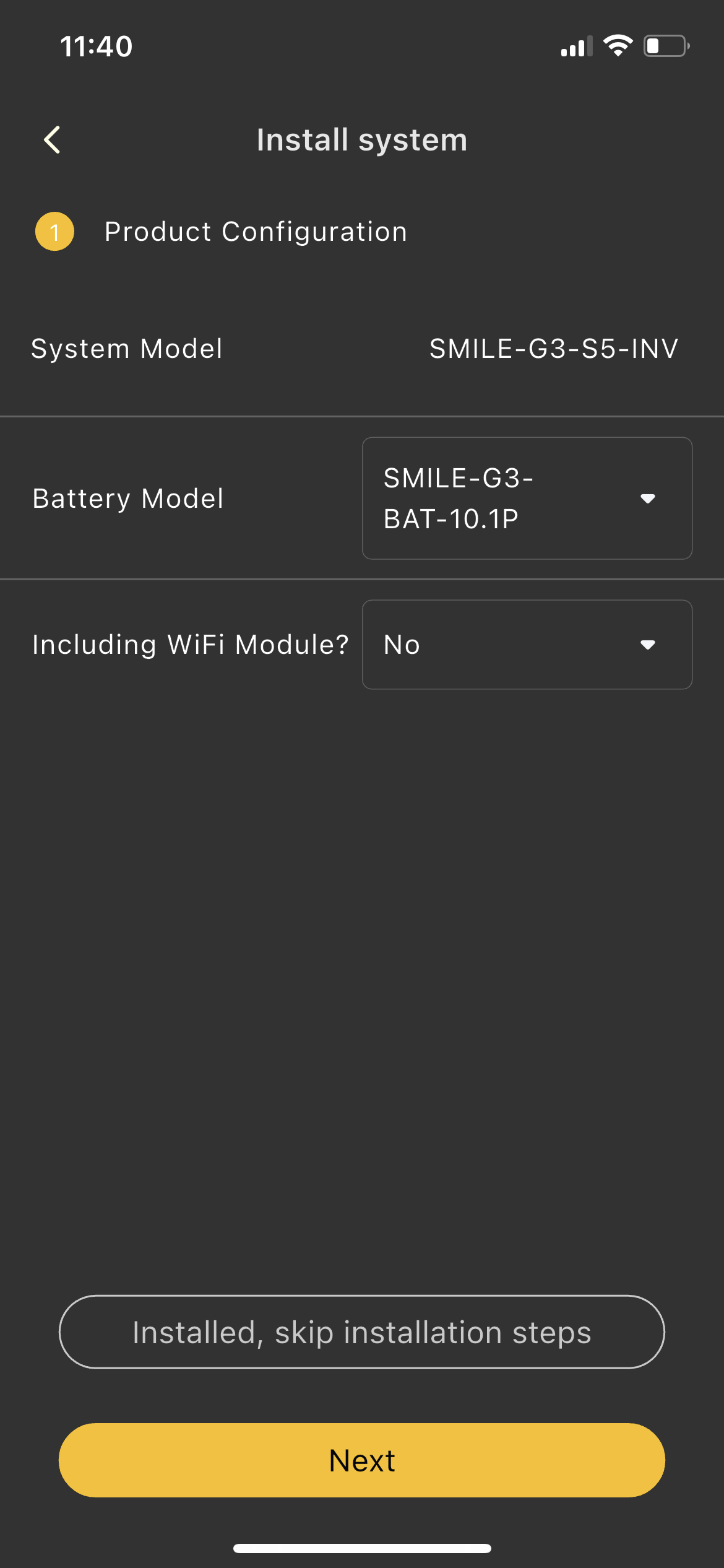
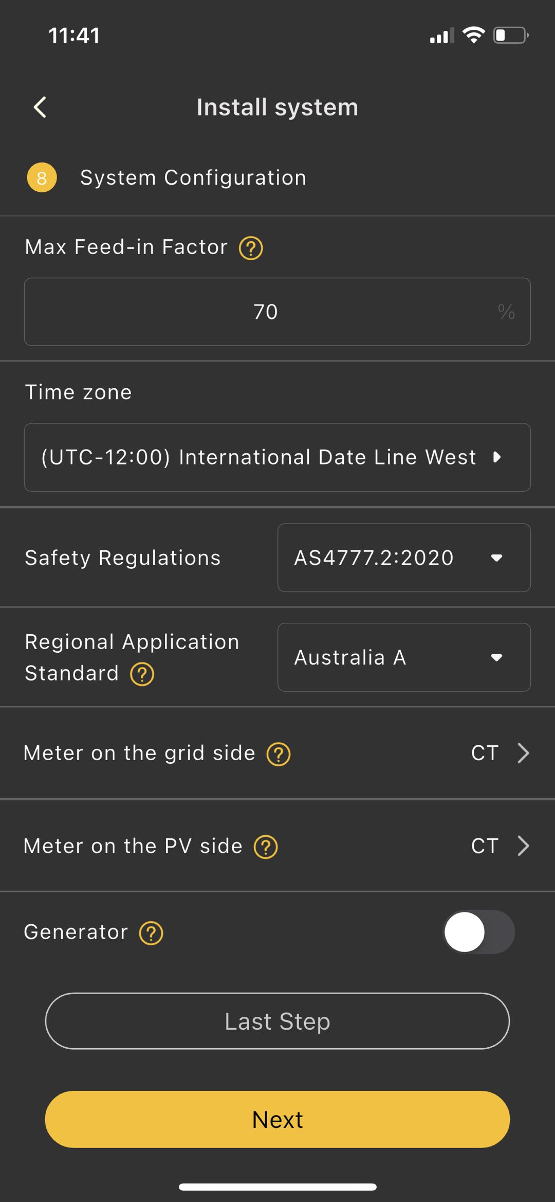
Figure 8-47 Check the installation configuration
Step 2:
Select the "P1 Meter" type in the grid-side electricity meter.
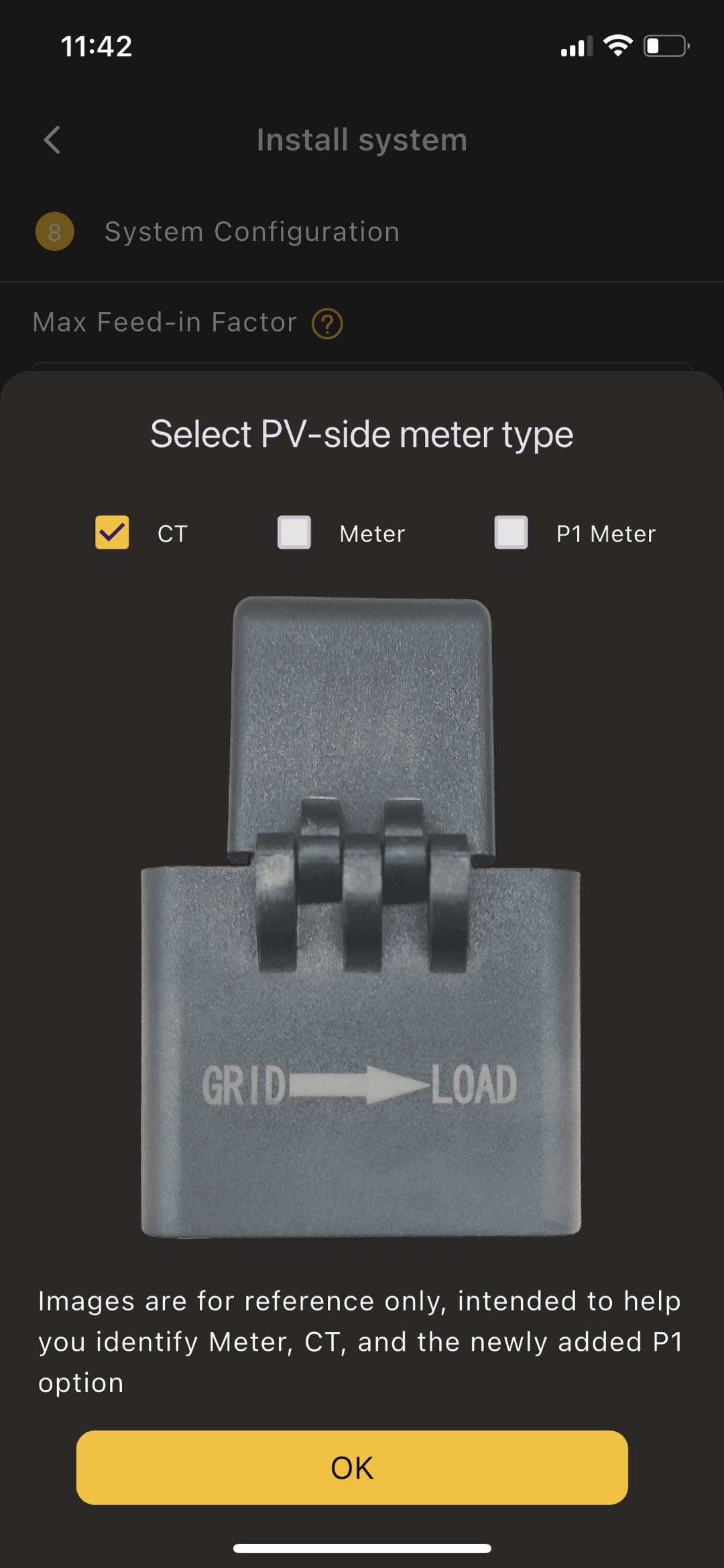
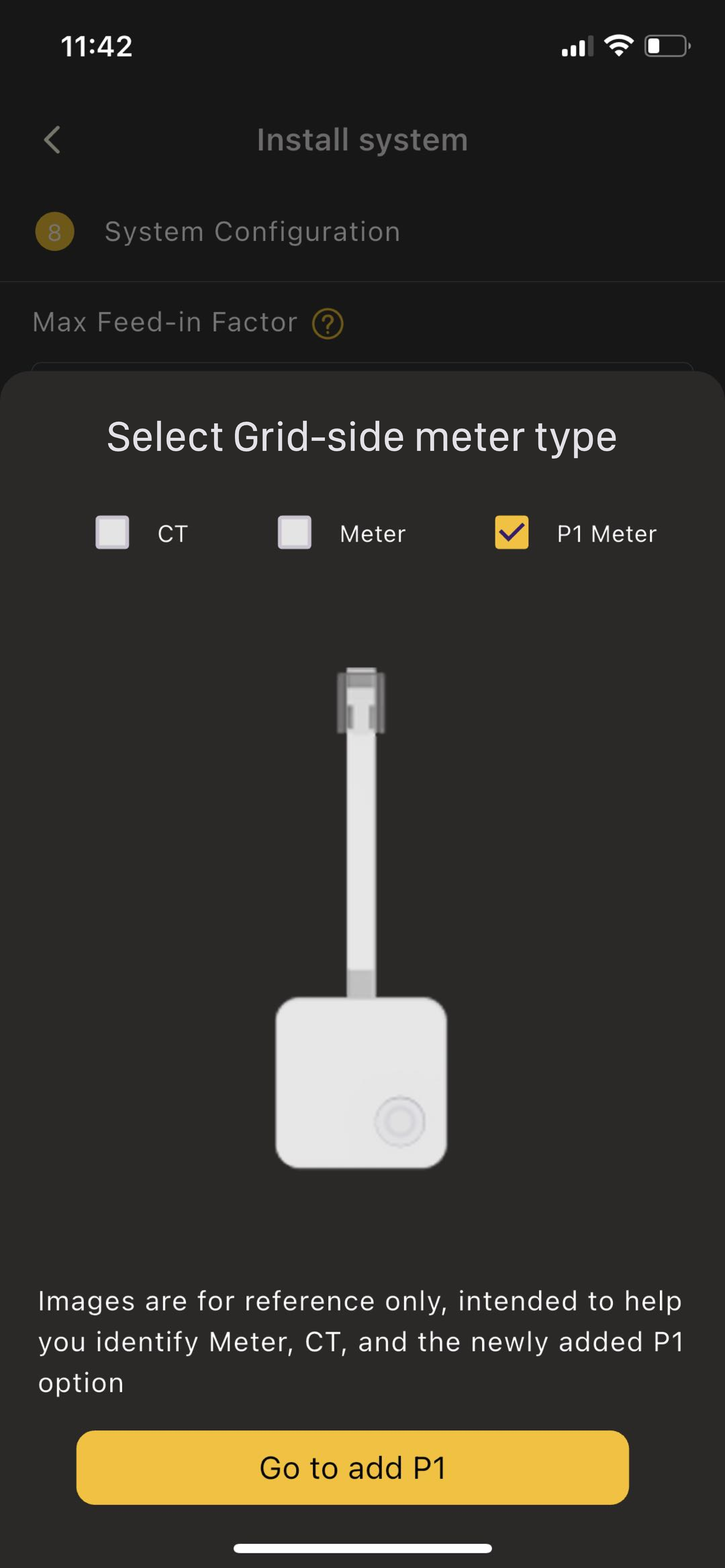
Figure 8-48 Select "P1 Meter"
Step 3:
Proceed to add, and select the addition method:
Method 1: Scan the QR code on the P1 Reader.
Method 2: Search for nearby P1 Reader via Bluetooth.
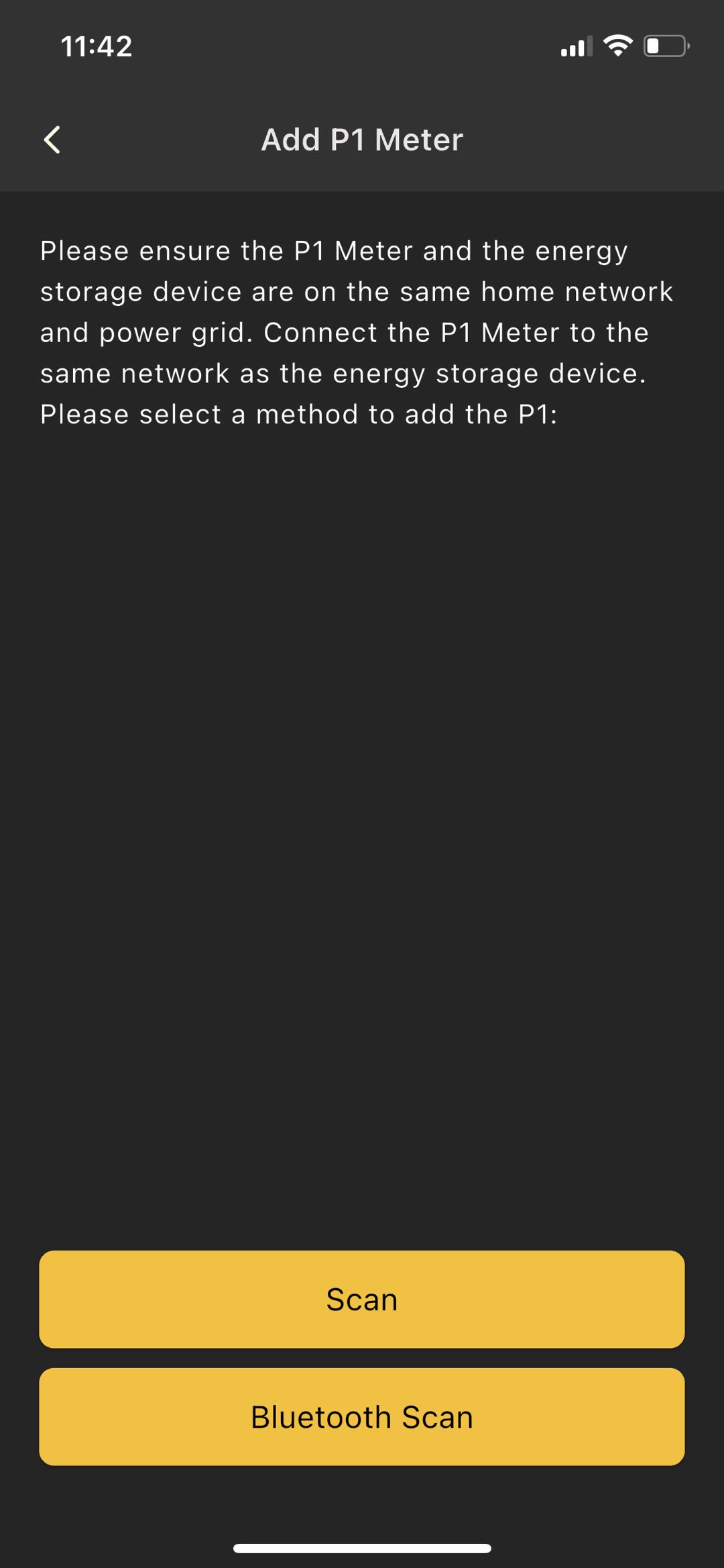
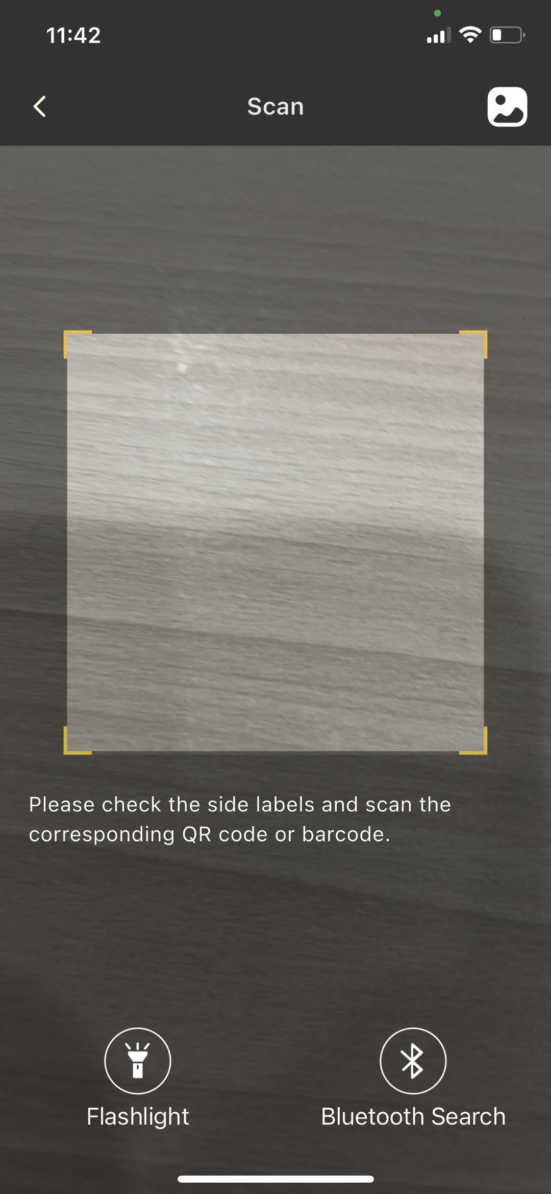
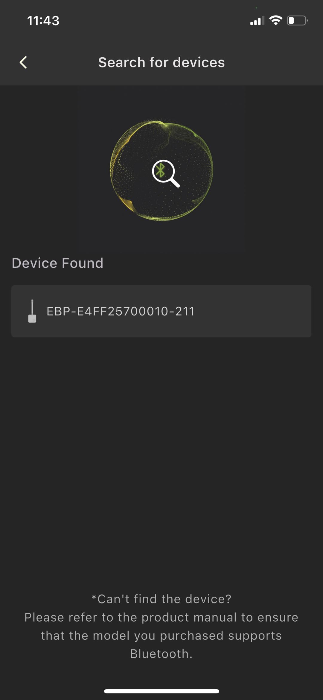
Figure 8-49 Add "P1 Meter"
Step 4:
Input pairing code.
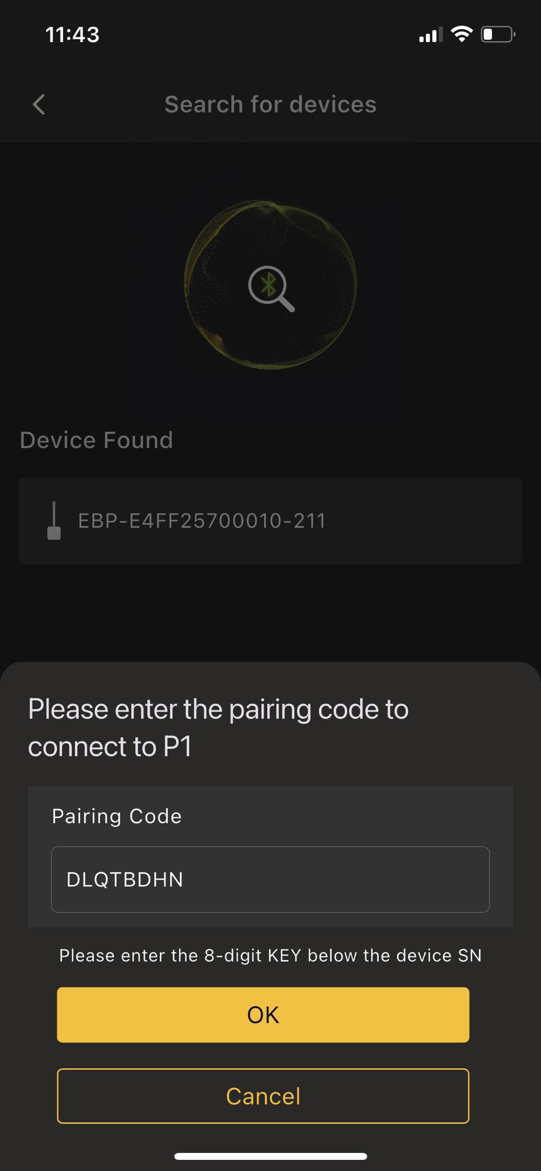
Figure 8-50 Input pairing code
Step 5:
Connect to Wi-Fi, then manually select the Wi-Fi name and enter the password.
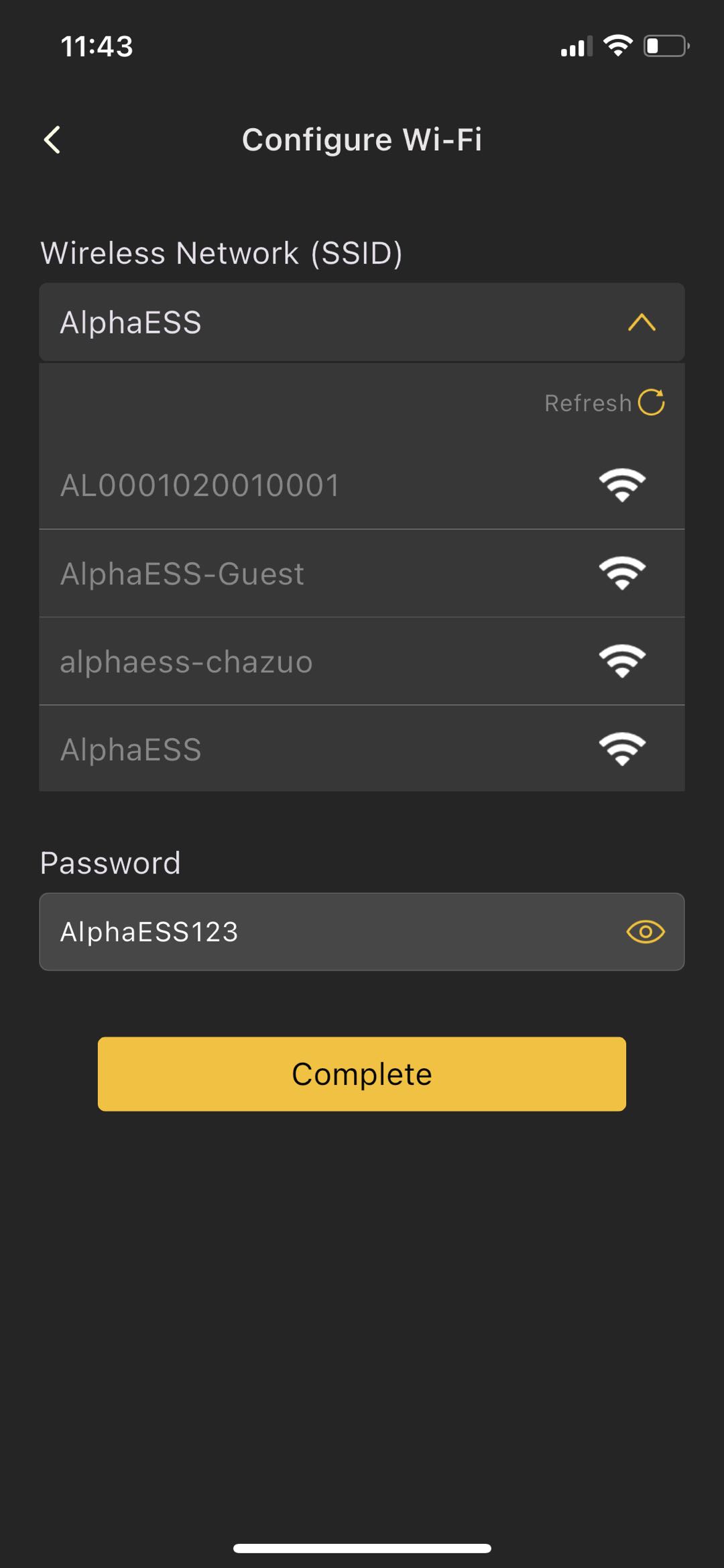
Figure 8-51 Connect to Wi-Fi
Step 6:
Click "Finish" and wait for the App to prompt "P1 has been successfully launched".
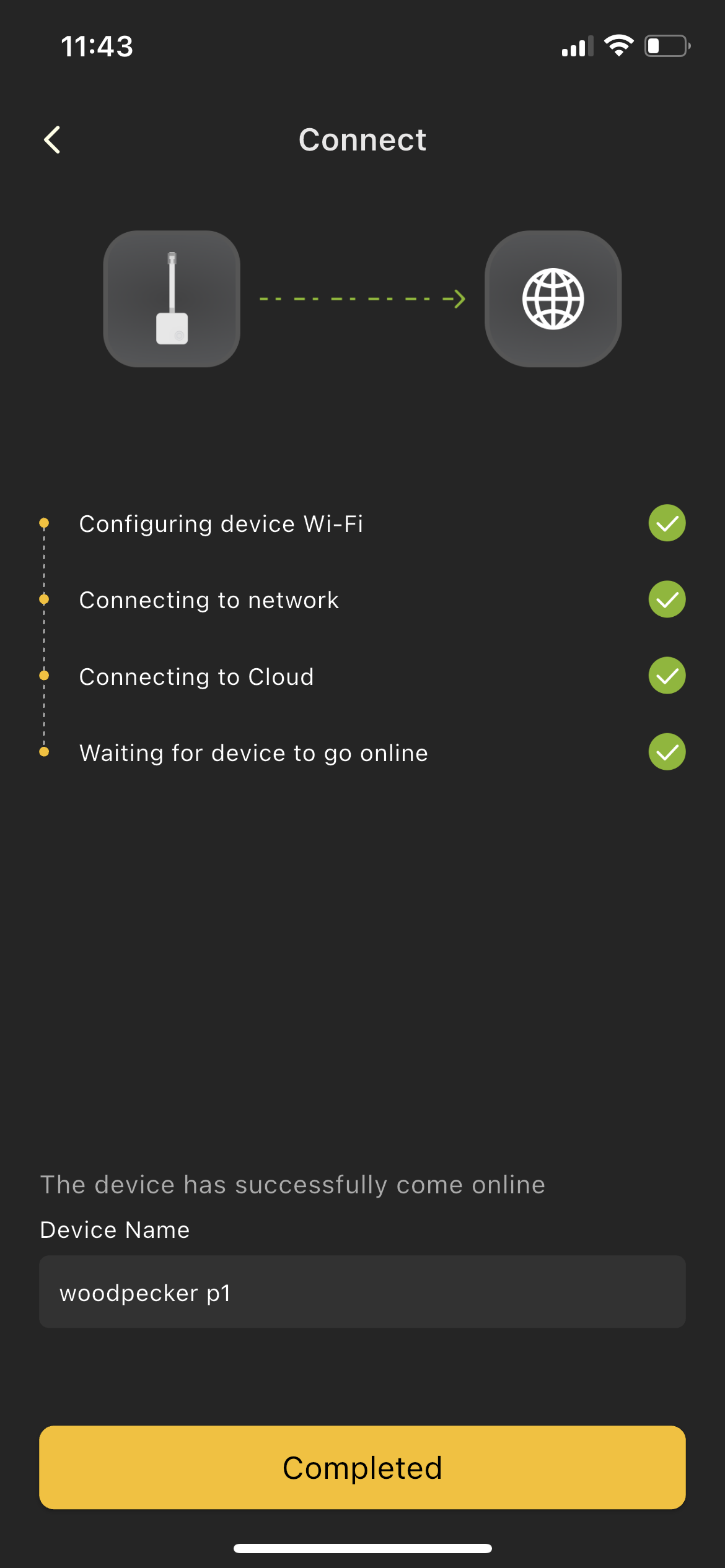
Figure 8-52 Connection Completion Diagram
Step 7:
Return to the configuration page, confirm that the P1 information is displayed (electric meter name, serial number, grid data), and complete the P1 configuration.
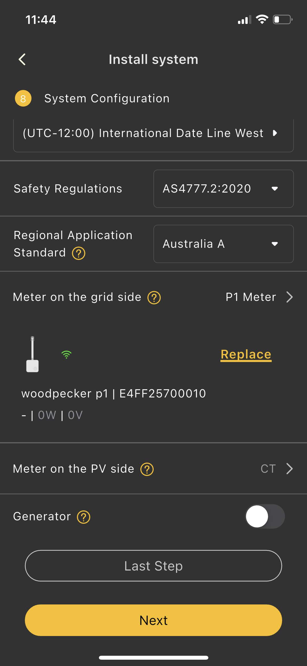
Figure 8-53 Confirm that the P1 information has been displayed