

Product Introduction and Application Scenarios
Naming Convention
SMILE-G3-T10
Location | Name | Explanation |
1 | SMILE | Residential energy storage system |
2 | G3 | 3rd Generation of SMILE series |
3 |
|
|
Complete Designation | Designation in This Document |
SMILE-G3-T4-INV SMILE-G3-T5-INV SMILE-G3-T6-INV SMILE-G3-T8-INV SMILE-G3-T10-INV SMILE-G3-T12-INV SMILE-G3-T15-INV | Energy storage inverter |
SMILE-G3-BAT-3.8S SMILE-G3-BAT-4.5S SMILE-G3-BAT-9.3S | Series battery |
SMILE-G3-T4 SMILE-G3-T5 SMILE-G3-T6 SMILE-G3-T8 SMILE-G3-T10 SMILE-G3-T12 SMILE-G3-T15 | Energy storage system / System |
System Introduction
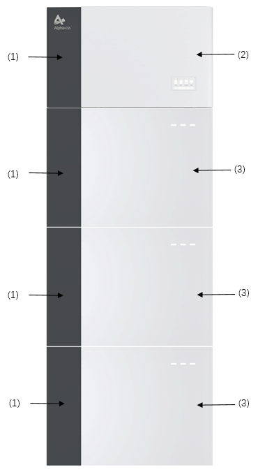
Figure 3-1 System product diagram
Object | Name | Explanation |
|
|
|
|
SMILE-G3-T5-INV
|
|
|
|
|
Product Description
Inverter Electrical Interface & Connections Introduction
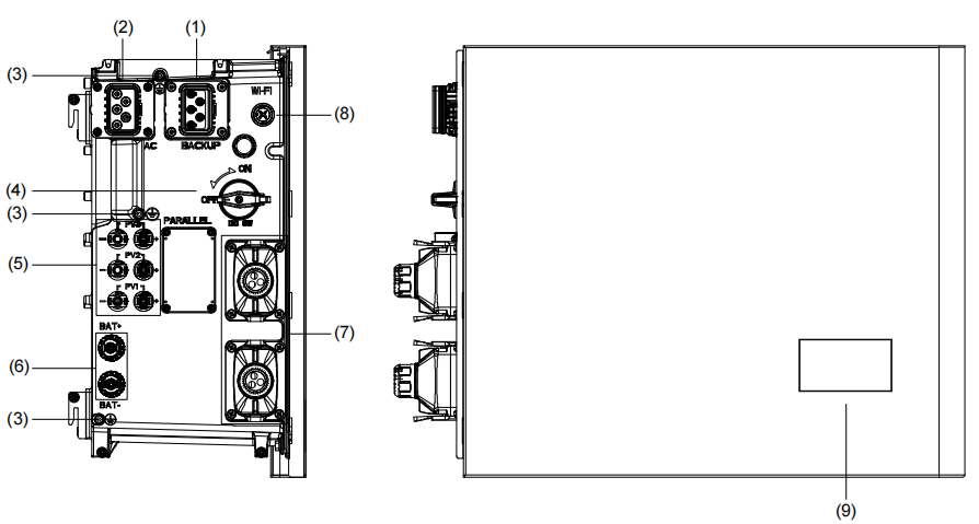
Figure 3-2 Inverter electrical interface diagram
Position | Designation |
1 |
|
2 |
|
3 |
|
4 |
|
5 |
|
6 |
|
7 |
|
8 |
|
9 |
|
* PV switch of the inverter is switched off when shipped.
** The DRM is only for regions with AS/NZW 4777.2 safety regulations.
Inverter Display Interface Introduction
LED Display
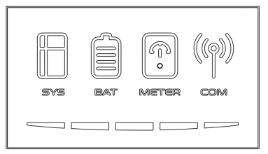
Figure 3-3 LED display
These LED indicators provide information about the operation status of the energy storage system.
Status | Explanation | Status | Explanation |
| White light The system works normally |
| White light The battery works normally |
| Red light The system is in fault |
| No light The battery is in fault |
| White light Meter communication works normally |
| White light Connected to the server |
| Flashing when SYS is white The system is in UPS mode Flashing or No light when SYS is red Meter lost |
| No light Disconnected to the server |


The lower five LED indicators provide information about the State of Charge (SOC) of the batteries connected to this energy storage system.
| Status | Explanation |

| White LED is off | |

| White LED is flashing | |

| White LED is glowing |
| LED Indicator | SOC | Description |
| LEDs show the SOC of batteries |  | SOC≤5% |
 | 5%<SOC≤20% | |
 | 20%<SOC≤40% | |
 | 40%<SOC≤60% | |
 | 60%<SOC≤80% | |
 | 80%<SOC≤100% |
Note that the LED lights provide an approximation of the State of Charge and should be read as an indication and not as a set value.
Battery Display Interface Introduction
During normal operation of battery, three LED indicators on the front cover provide information the State of Charge (SOC) of the battery with white lights glowing and off or flashing (0.5s on, 1.5s off).
LED Indicator | No. | SOC | Description |
|
|
| |
|
| ||
|
| ||
|
| ||
|
| ||
|
|


State Display
The LEDs indicate the operating state of the product.
Standby: All white LEDs are flashing (0.5s on and 0.5s off).Normal: White LEDs are glowing or flashing (0.5s on and 1.5s off).Protection: Yellow LEDs are glowing or flashing (0.5s on and 0.5s off).Error: Yellow LEDs are glowing or flashing (0.5s on and 0.5s off).Shutdown: All LEDs are off.
Battery Introduction of SMILE-G3-BAT-3.8S
Battery appearance and dimensions
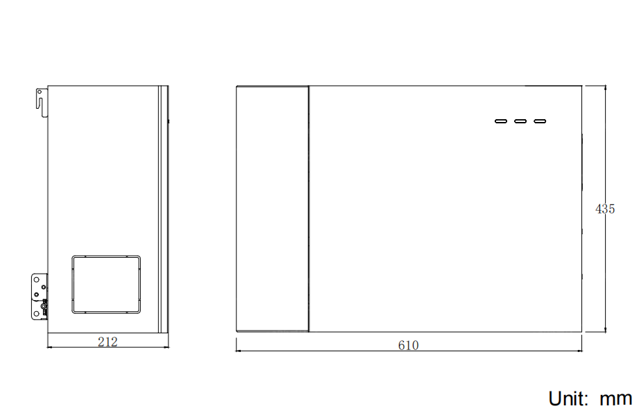
Figure 3-4 Battery appearance and dimensions
Connection area overview
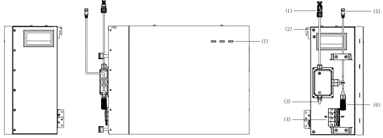
Figure 3-5 Connection area overview
| Position | Designation |
| 1 | Battery Positive Connector |
| 2 | Grounding Point |
| 3 | Battery Negative Connector |
| 4 | Battery Circuit Breaker |
| 5 | BMS COM1 |
| 6 | BMS COM2 (with Terminal Resistor) |
| 7 | LED Display |
Battery Introduction of SMILE-G3-BAT-4.5S
Battery appearance and dimensions
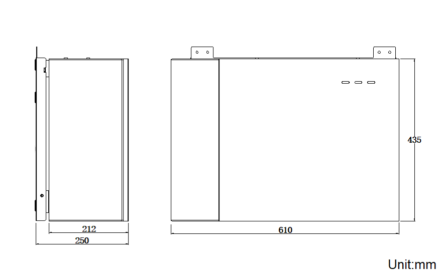
Figure 3-6 Battery appearance and dimensions
Connection area overview
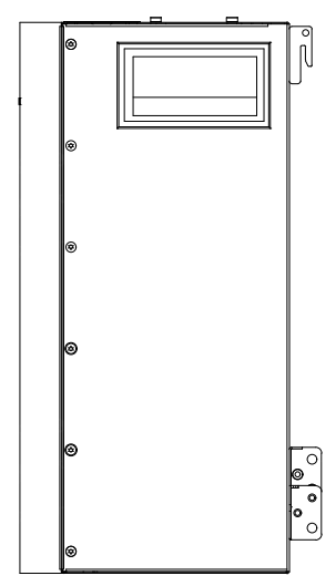
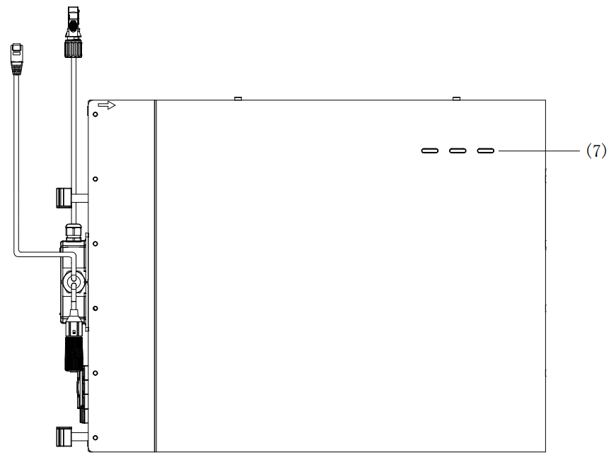
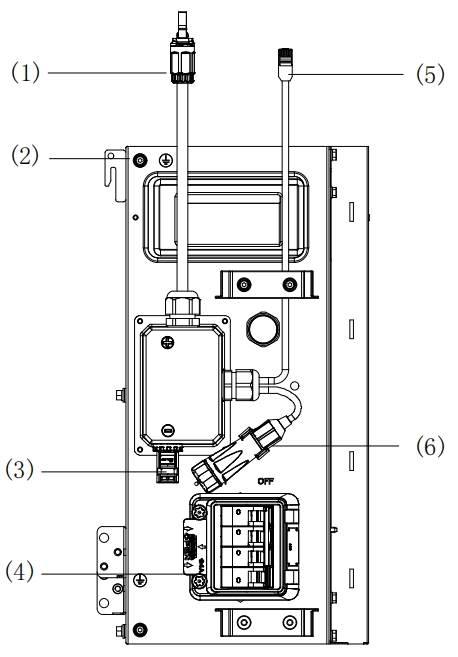
Figure 3-7 Connection area overview
| Position | Designation |
| 1 | Battery Positive Connector |
| 2 | Grounding Point |
| 3 | Battery Negative Connector |
| 4 | Battery Circuit Breaker |
| 5 | BMS COM1 |
| 6 | BMS COM2 (with Terminal Resistor) |
| 7 | LED Display |
Battery Introduction of SMILE-G3-BAT-9.3S
Battery appearance and dimensions
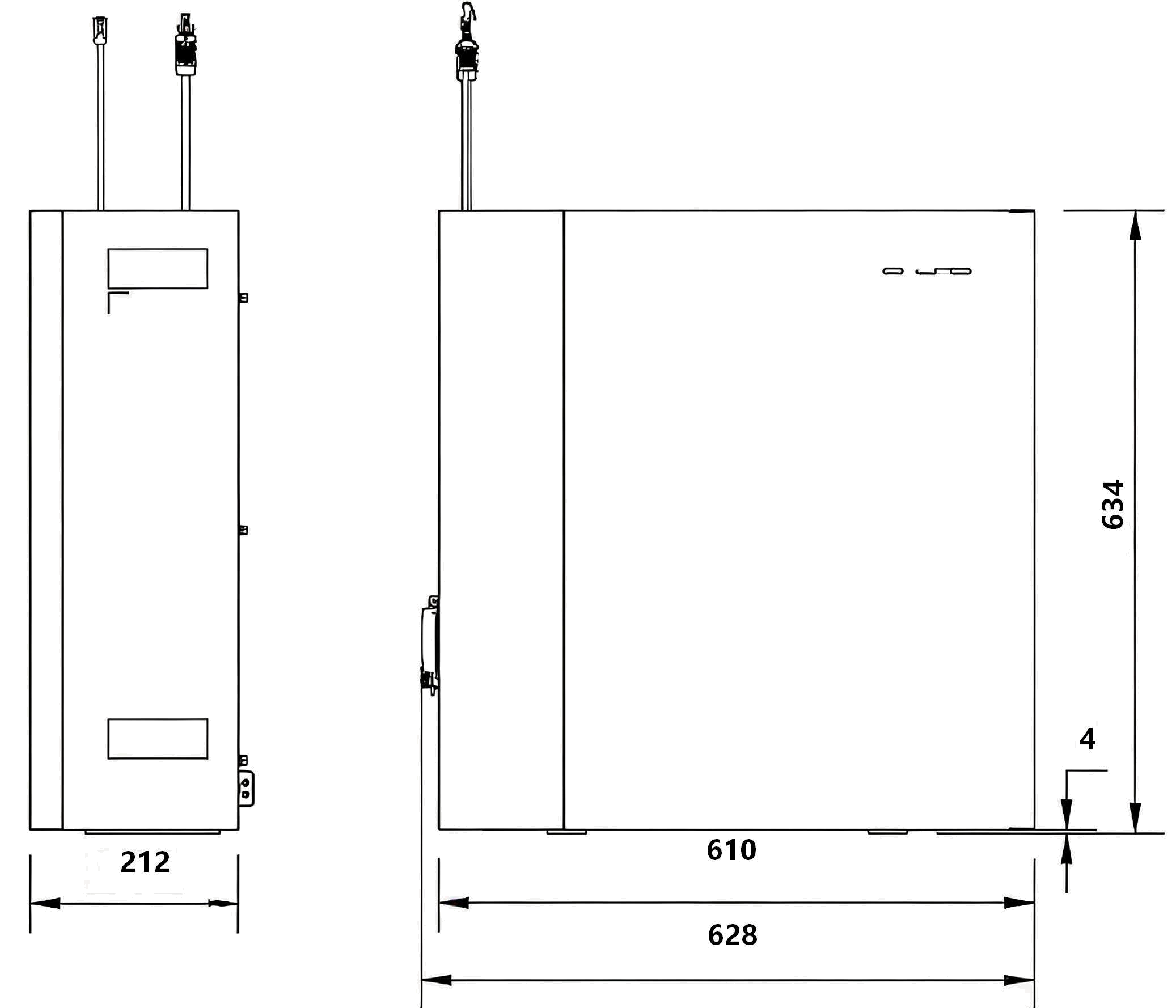
Figure 3-8 Battery appearance and dimensions
Connection area overview
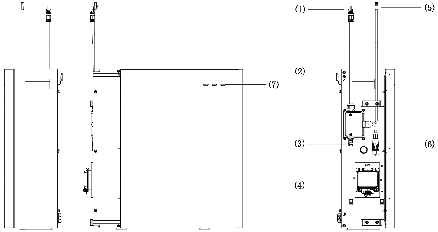
Figure 3-9 Connection area overview
| Position | Designation |
| 1 | Battery Positive Connector |
| 2 | Grounding Point |
| 3 | Battery Negative Connector |
| 4 | Battery Circuit Breaker |
| 5 | BMS COM1 |
| 6 | BMS COM2 (with Termination Resistor) |
| 7 | LED Display |
Application Scenarios
SMILE-G3 three phase system (includes inverter SMILE-G3-T4/T5/T6/T8/T10/T12/T15-INV, battery SMILE-G3-BAT-3.8S, SMILE-G3-BAT-4.5S and SMILE-G3-BAT-9.3S) can be connected as a DC-Coupled systems (mostly new installation), AC-Coupled systems (mostly retrofit), Hybrid-Coupled systems (mostly retrofit, and increase the PV capacity), and Off-Grid (under development) systems as shown in the following diagrams:
DC-Coupled Energy Storage System
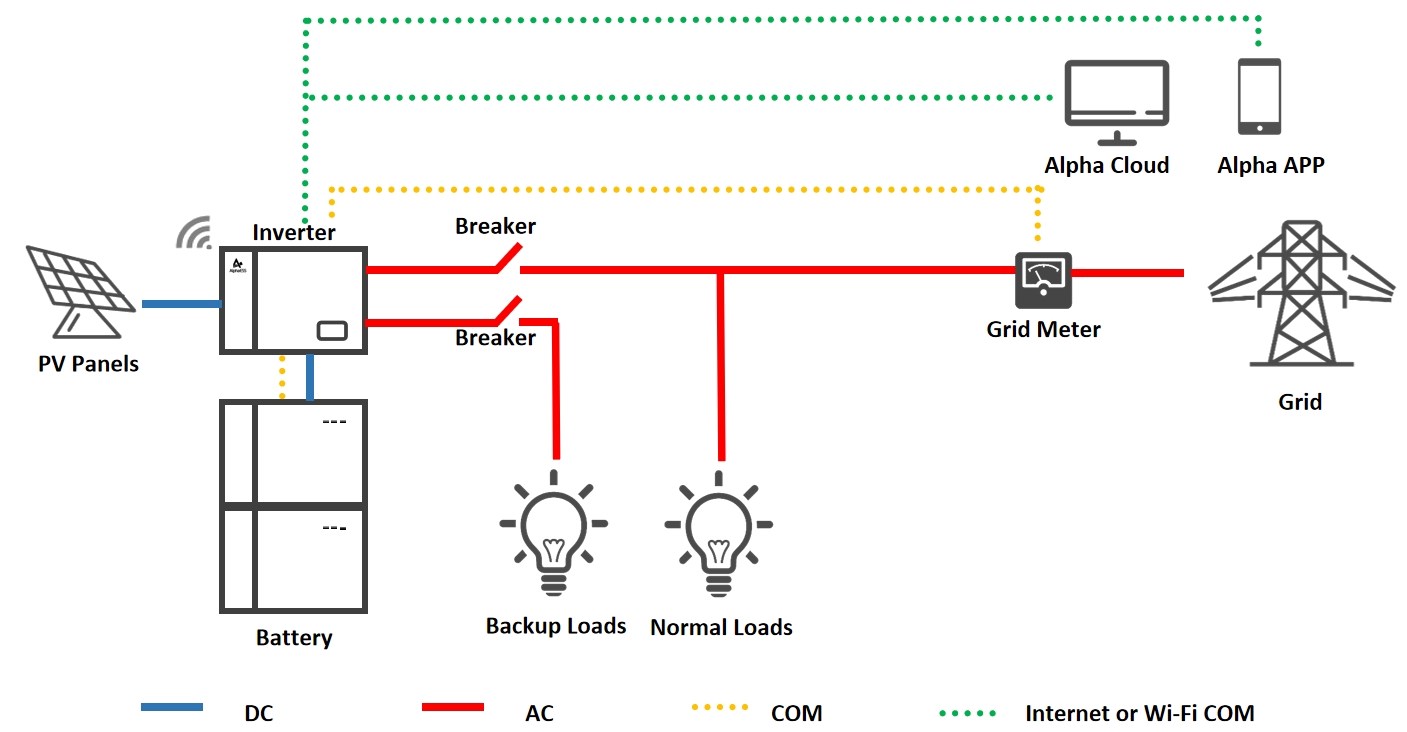
Figure 3-10 DC-Coupled Storage System – Scheme
AC-Coupled Energy Storage System
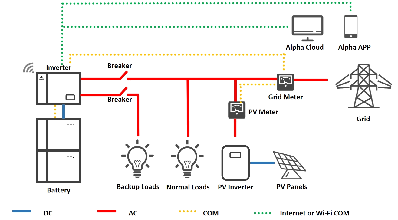
Figure 3-11 AC-Coupled Storage System – Scheme
Hybrid-Coupled Energy Storage System
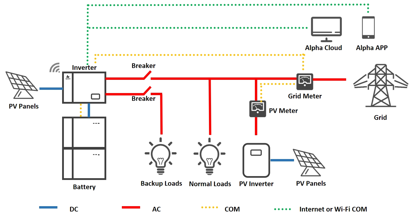
Figure 3-12 Hybrid-Coupled Storage System – Scheme
NOTES:
In all cases, Normal Loads and Backup Loads must be appropriately protected by earth fault protection devices (e.g. Type A or Type B RCDs, RCBOs) in accordance with appropriate Standards.
Normal/Backup Loads should not exceed the rated capacity of the inverter, even during on-grid operation.
While the GRID RLY and Backup RLY are open, the Bypass RLY is closed, the inverter will be in Bypass mode and functions properly.