

Mounting
Checking the Outer Packaging
Before unpacking the product, check the outer packaging for damage, such as holes, signs of mechanical damage or water damage. If any damage is found, do not unpack the product and contact your dealer as soon as possible.
Scope of Delivery
Check the scope of delivery and inspect components to ensure they are present and undamaged.
Contact your distributor if the packed components are incomplete or damaged.
SMILE-G3-T4/T5/T6/T8/T10/T12/T15 Inverter | ||||
|
|
|
|
|
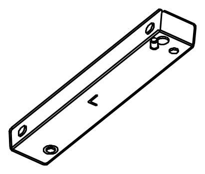
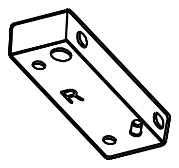
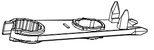
Inverter (×1) | TOP Cover (×1) | Right Cover (×1) | Cable Cover (×1) | Left Support Foot (×1) |
|
|
|
|
|
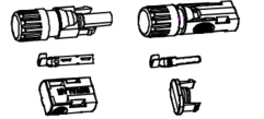
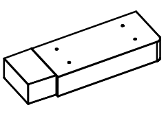
Right Support Foot (×1) | PV+ & PV- Connector&Blocking Cover(×3) | Grid Connector (×1) | Backup Connector (×1) | Wi-Fi Dongle (×1) |
|
|
|
|
|
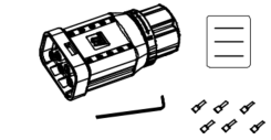
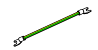
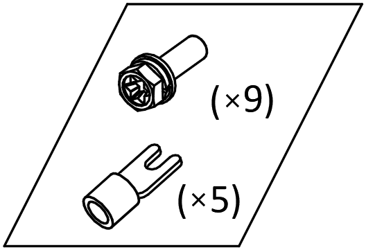
AUX Terminal Block (×1) | BAT Power Cable (×2) | Communication Cable Between Two Column Series Batteries (×1) | Grounding Cable (×1) | Screws and Terminals Set (×1) |
|
|
|
| |
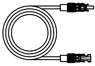
Documents (×4) | PV removal Tool (×1) | BAT Removal Tool (×1) | Grid & Backup Removal Tool (×1) | |
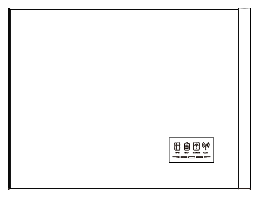
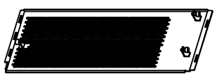
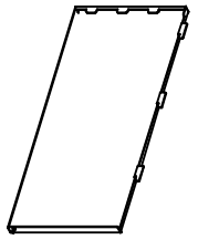
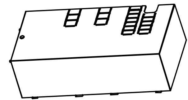
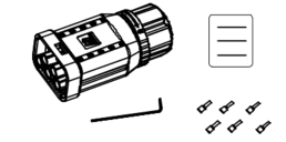

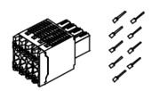
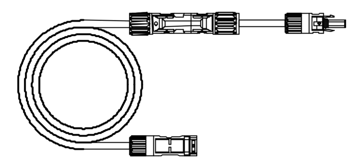
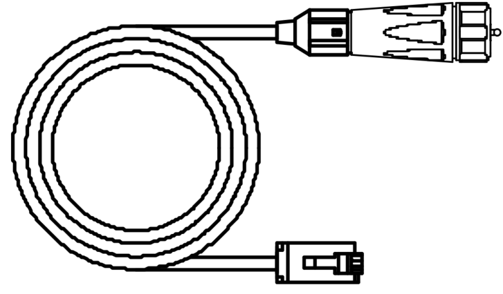



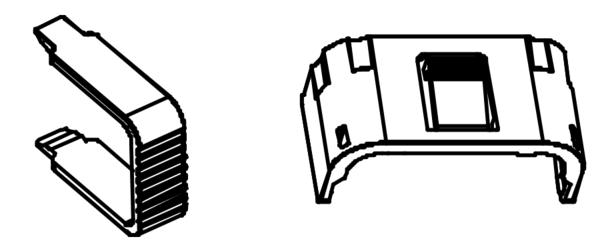
(Optional) Accessories of Inverter for Wall Mounting | |||
|
|
|
|
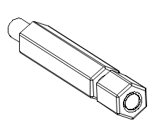
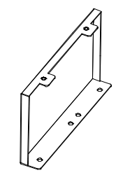
Wall Bracket (×1) | Support Stud for Right Cover (×1) | Support Plate for Cable Cover (×1) | Support plate for cable cover (×1) |
|
|
|
|
Hooks for Wall Bracket (×4) | Wall Anchor ST6*55 (×4) | Screw M4*10(×2) | Hexagon Head Screw M5*12 (×8) |
|
|
|
|
Connector for Wall Brackets (×2) | Series Battery Main Positive Power Cable for 4.5S/9.3S (×1) | Series Battery Main Positive Power for 3.8S (×1) | Communication Cable between Inverter and 1st Series Batteries (×1) |
| |||
Series Battery Main Negative Power Extension Cable (×1) | |||

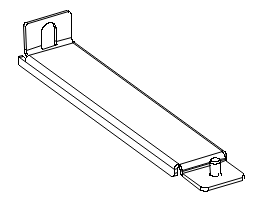


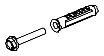
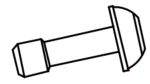
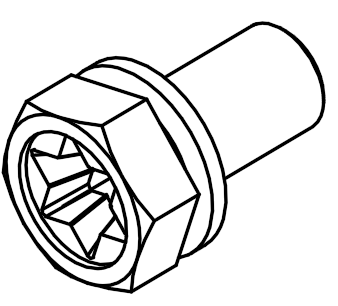

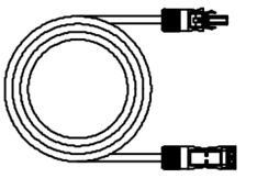
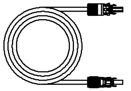
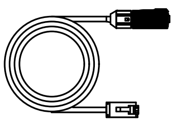

SMILE-G3-BAT-3.8S/4.5S | |||
|
|
|
|
Battery (×1) | Battery Cable Cover (×1) | Wall Bracket (×1) | Grounding Bar (×1) |
|
|
|
|
Wall Anchor ST6*55 (×6) | Hexagon Head Large Washer Screw M5*12 (×3) | Flange Nut M5 (×7) | Quick Installation Guide (×1) |


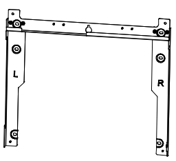




(Optional) Cables for Distanced Horizontal Battery Expansion of SMILE-G3-BAT-3.8S | ||||
|
|
|
|
|
Main Negative Power Extension Cable (×1) | Communication Cable between two Column Series Batteries (×1) | Power Cable between two Column Series Batteries (×1) | M5 Y Type Terminal (×3) | Connector removal wrench (×1) |

| ||||||
Top Cover (×1) | Top Cover Bracket (×2) | Hexagon Head Screw M5*12(×5) | Countersunk Head Screw M4*8 (×5) | |||
SMILE-G3-BAT-9.3S | ||||||
|
|
|
| |||
Battery (×1) | Battery Cable Cover (×1) | Top Bracket (×1) | Grounding Bar (×1) | |||
|
|
|
| |||
Quick Installation Guide (×1) | Position Plate (×1) | Wall Anchor ST6*55 (×4) | M5 Y Type Terminal (×2) | |||
|
|
|
| |||
BAT Connector Disassembling Tool (×1) | Hexagon Head Screw M5*12 (×4) | Connecting Plate (×2) | Countersunk Head Screw M5 * 8 (×2) | |||
|
|
|
| |||
Communication Cable (×1) Code: A | Power Cable (×1)Code: B | Power Cable (×1) Code: C | Power Cable (×1) Code: D | |||

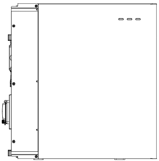

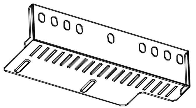
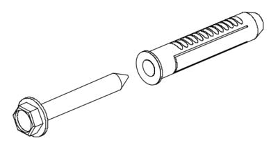
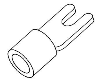
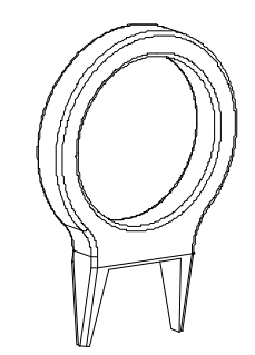
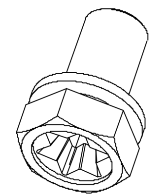


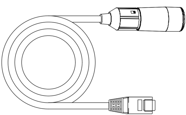
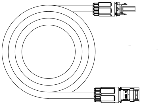

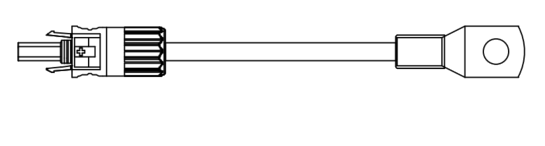
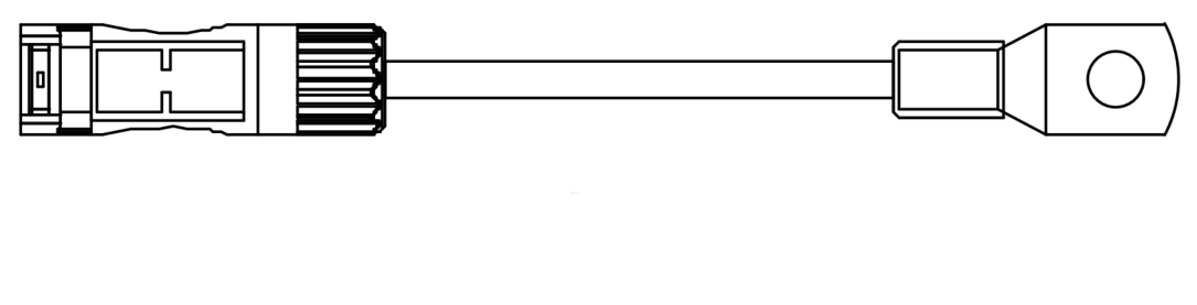
a: For batteries top connection during batteries forward expansion mounting.
b: Only applicable to Australia and New Zealand.
c: Connect to SMILE-G3 single phase inverter with M6 OT battery connection terminals.
Only provide for Australia and New Zealand markets.
(Optional)Battery Base Unit of SMILE-G3-BAT-3.8S/4.5S/9.3S | |||
|
|
|
|
Base Unit (×1) | Fixing Brackets (×2) | Right Connection Block (×1) | Wall Anchor ST6*55 (×4) |
|
|
|
|
Hexagon Head Screw M5*12 (×10) | Quick Installation Guide (×1) | Right Connection Plate (indoor) (×4) | Hexagon Head Limit Screw M5*10 (×9) |
|
|
|
|
Top Wall Bracket (×1) | Limit block (×8) | Pan Head Screw M5*10* (×9) | Right Connection Plate (outdoor) (×4) |
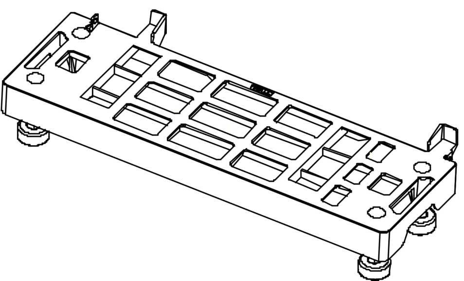
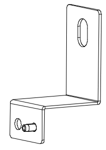
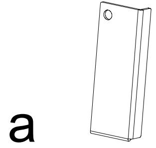
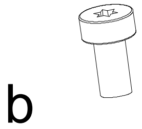
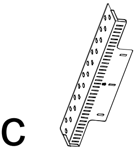

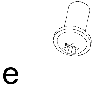
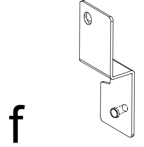
*a, b and c are for SMILE-G3-BAT-3.8S
*c, d, e and f are for SMILE-G3-BAT-4.5S
*f is for SMILE-G3-BAT-9.3S
Requirements for Mounting
DANGER
Danger to life due to fire or explosion
Despite careful construction, electrical devices can cause fires.
Do not mount the ESS in areas containing highly flammable materials or gases.
Do not mount the ESS in potentially explosive atmospheres.
Basic Requirements
SMILE-G3-T4/T5/T6/T8/T10/T12/T15-INV and SMILE-G3-BAT-4.5S and SMILE-G3-BAT-9.3S are suitable for indoor and outdoor installation. SMILE-G3-BAT-3.8S are only suitable for indoor installation.
Do not install the ESS in a place where people can easily touch it because the inverter’s surface will get extremely hot during operation.
Do not engage screws into tapped holes using a Hammer Driver, Impact Driver or “Rattle gun”. Do not damage screws or threaded holes by tightening with too much torque.
To ensure safety, children should not operate or be near the ESS unless supervised by an adult
Mounting Environment Requirements
DANGER
Danger to life due to fire or explosion
Despite careful construction, electrical devices can cause fires.
Do not mount the energy storage system in areas containing highly flammable materials or gases.
Do not mount the energy storage system in potentially explosive atmospheres.
Do not mount the ESS outdoors in areas of high salt mist likelihood where corrosion may cause damage. An area of high salt mist likelihood refers to a region within 500m from the coast or prone to the sea breeze.
Do not place the system near water sources such as downpipes or sprinklers.
The ESS must be mounted in a well-ventilated environment to ensure adequate heat dissipation.
Do not mount in a location that will be exposed to direct sunlight. Mount the ESS in a sheltered place or mount an awning over it. When mounted under direct sunlight, the power of the ESS may be derated due to additional temperature rise and the longevity of the product will be reduced.
Favour locations that are indoors, under cover, or generally protected from the elements and extreme temperatures (e. g. in a garage). If the ESS is mounted in the garage, ensure the product is adequately protected from potential mechanical impact.
In the UK , the energy storage battery shall be installed outdoors.
The optimal temperature range for the battery to operate is 15 to 30 ℃.
In the UK, If the energy storage batteries are installed within a dwelling area, an extra audible warning shall be used for battery persistent dangerous conditions.
In the UK , Batteries shall not be installed in any of the following locations:
Rooms in which persons are intended to sleep;
Routes used as a means of escape that are not defined as protected escape routes, including landings, staircases and corridors;
Corridors, shafts, stairs or lobbies of protected escape routes;
Firefighting lobbies, shafts or staircases;
Storage cupboards, enclosures or spaces opening into rooms in which persons are intended to sleep;
Outdoors (ground-mounted or wall-mounted in a suitable enclosure) within 1 m of:
escape routes;
doors;
windows; or
ventilation ports.
Voids, roof spaces or lofts;
Within 2 m of stored flammable materials and fuel storage tanks or cylinders;
Cellars or basements that have no access to the outside of the building.
In the UK, after the system is installed, the surrounding environment needs to be equipped with fire alarm or fire extinguishing devices in accordance with the BS EN54 standard.
In the UK, if the system is installed in areas prone to vehicle damage (such as garages, driveways, etc.), please install protective devices (such as protective barriers, protective enclosures, etc.) in these areas.
The flash arcs of the SMILE-G3-BAT-4.5S and SMILE-G3-BAT-9.3S batteries are both below 3 cal/cm^2 (using the calculation method described in AS/NZS 5139). Therefore, tools are required when contacting the battery cells in the UK.
Mounting Structure Requirements
The surface to which the ESS is to be mounted shall be fire-rated where required by local regulations.
Out of an abundance of caution, it is recommended that the system be mounted on non-flammable building materials, even when not required by local regulations.
Ensure that the mounting surface is sufficiently sturdy to bear the weight of the product.
In residential installation, do not mount the system on drywalls or walls made of gyprock or similar materials with poor sound insulation. The noises generated by the inverter can be noticeable and may be exacerbated by locations with poor insulation or where echoing may occur.
The mounting location must be suitable for the weight and dimensions of the product (see Section 5.3.5).
Mounting Angle and Stack Requirement
The battery should be mounted on the base unit or hanged on the wall bracket and secured to the wall.
The inverter should be placed on the top of the battery and secured to the battery.
The installation angle requirement is as follows: do not mount the inverter at forward-tilted, side-tilted, horizontal, or inverted positions.
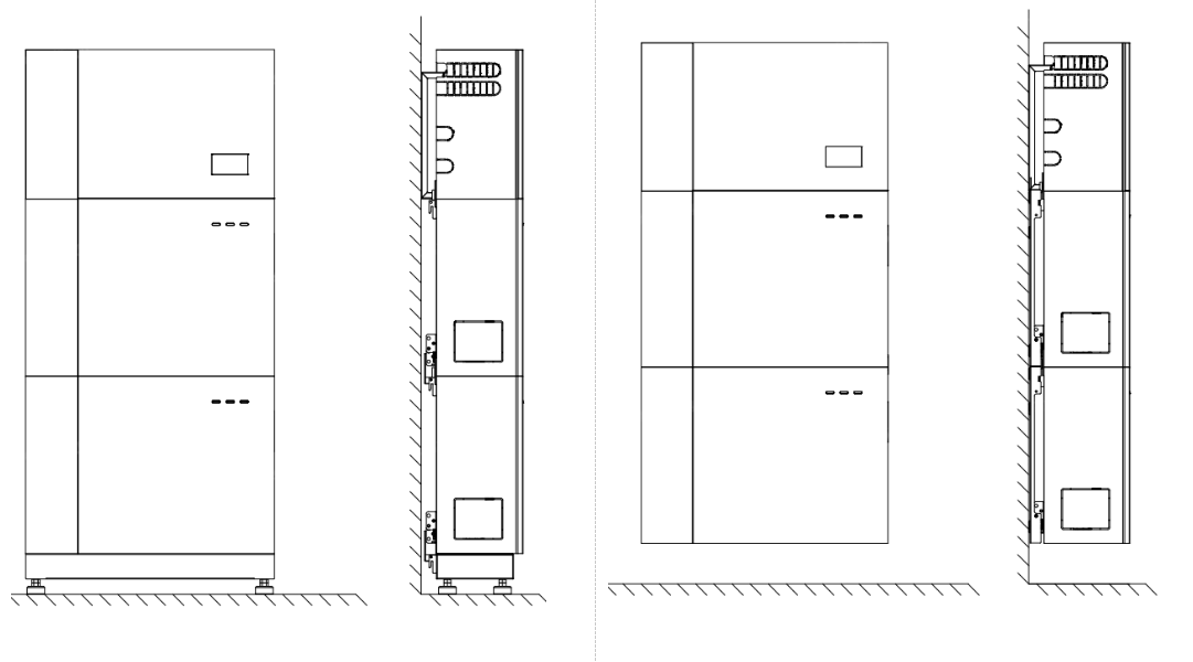
Figure 5-1 Product installation diagram
Mounting Space Requirements
Reserve sufficient space around the energy storage system to ensure sufficient space for installation, maintenance and heat dissipation.
Recommend a minimum of 100 mm off the ground was advisable to protect from submergence, so the series batteries should be mounted by wall brackets or base unit.
The side clearance is a recommendation which can be adjusted according to the end-users requirements. Clearances may be up to 100mm less than noted if ventilation is adequate and no restrictions or objects will limit access to the labelling or switches of the Product or to the use of tools to remove covers or service/remove the Product.
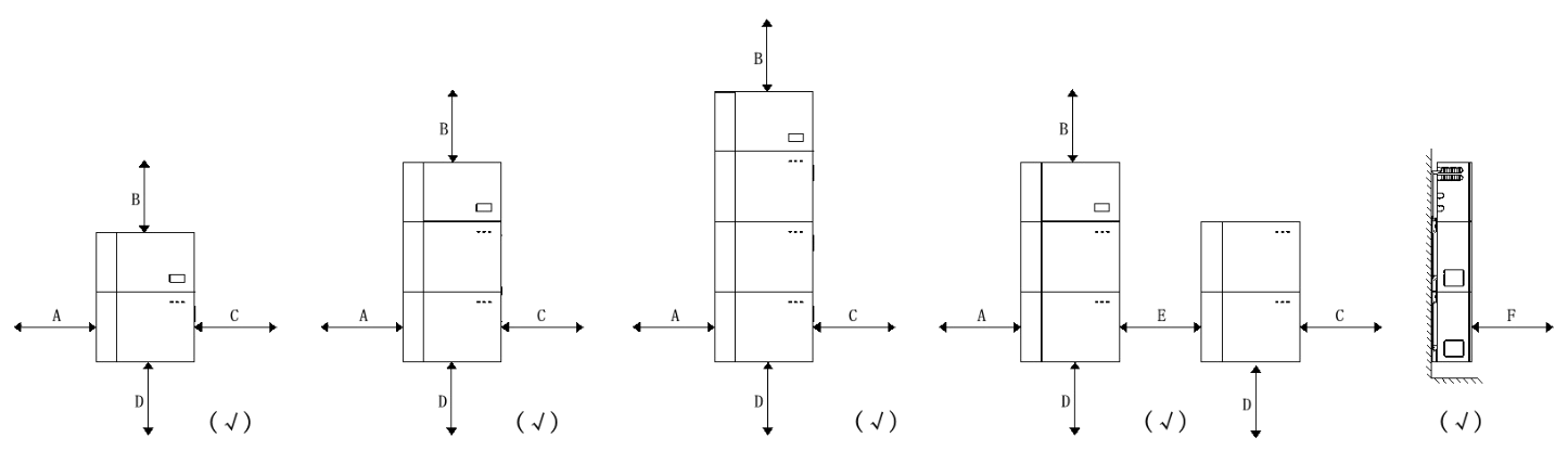
Figure 5-2 Installation space requirements
| Position | Distance (Unit: mm) |
| A | ≥300 |
| B | ≥300 |
| C | ≥300 |
| D | ≥200 |
| E | ≥300 |
| F | ≥100 |
Note: Local Standards may add additional clearance requirements, particularly regarding clearances between the ESS and other Electrical Appliances.
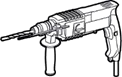
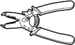
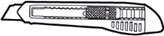
Preparing Tools and Instruments
Category | Tools and Instruments | ||
Installation |
|
|
|
|
|
| |
|
|
| |
|
|
| |
|
|
| |
|
|
| |
|
|
| |
|
|
| |
|
|
| |
|
|
| |
|
| ||
|
|
|
|
|
|
| |
| |||







Mounting the System
Mounting the Series Battery SMILE-G3-BAT-3.8S/4.5S/9.3S
Note: The following battery installation instructions only list the general steps. There may be slight differences for each battery. Install the battery using the 9.3S battery as an example.
Mounting the Battery with Base Unit
When mounting battery SMILE-G3-BAT-3.8S/4.5S/9.3S with base unit, please follow the below steps.
Take out the base unit, place it on the floor, and level it using a spirit level. Refer to 1 in Figure 5-3.
Release the base unit clip and place the first battery onto the base unit. Refer to 2 in Figure 5-3.
Tighten the M5 screw into the limit hole. (tool: T20 screwdriver, torque: 2.5 Nm). Refer to 3 in Figure 5-3..
Tighten the base unit to the battery using the connection plate. (tool: T20 screwdriver, torque: 2.5 Nm). Refer to 4 in Figure 5-3.
Position the wall bracket at the top of the battery, aligning it with the battery's mounting holes. Mark the contact points against the wall using a marker pen. Refer to 5 in Figure 5-3.
Cover the top of the battery with the packaging bag. Using a hammer drill, bore holes along the previously marked positions on the wall. Drive the expansion plugs into the holes using a hammer, then remove the packaging bag. Refer to 6 in Figure 5-3.
Secure the wall bracket and the top of the battery using M5 screws. (tool: T20 screwdriver, torque: 2.5 Nm). Refer to 7 in Figure 5-3.
Screw the ST6 into the expansion nut. (tool: SW8, torque: 6 Nm). Refer to 8 in Figure 5-3.
Place the second battery on top of the first battery, ensuring the battery switch is closed. Refer to 9 in Figure 5-3.
Secure the grounding bar between the two batteries. (tool: T20 screwdriver, torque: 2.5 Nm). Refer to 10 in Figure 5-3.
Repeat steps 5 to 8 to complete the installation of two batteries.
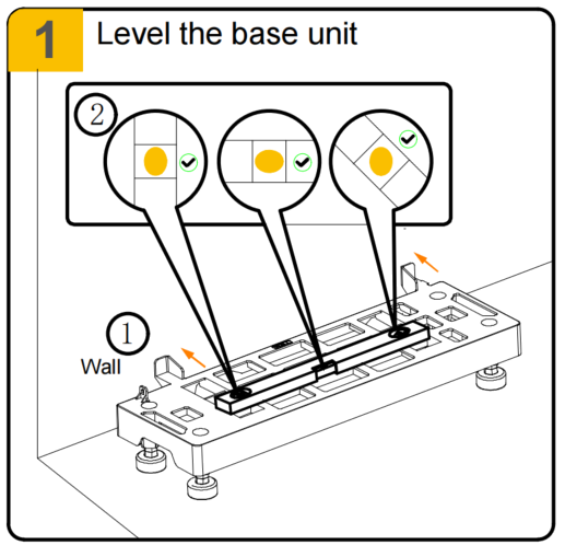
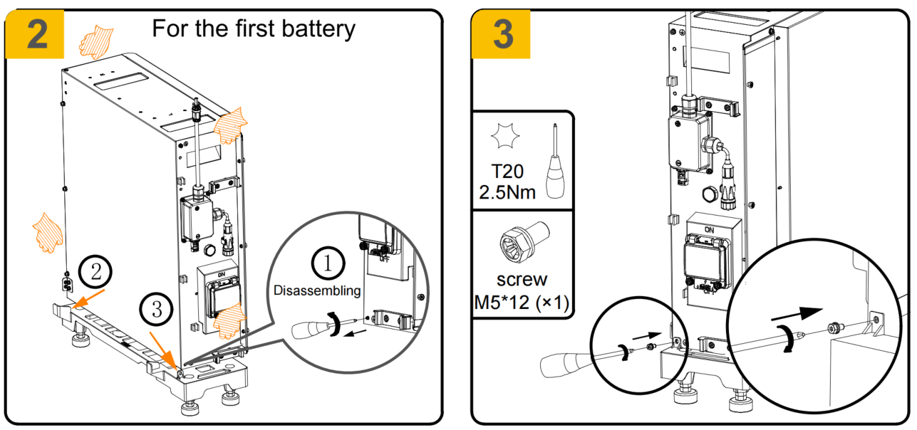
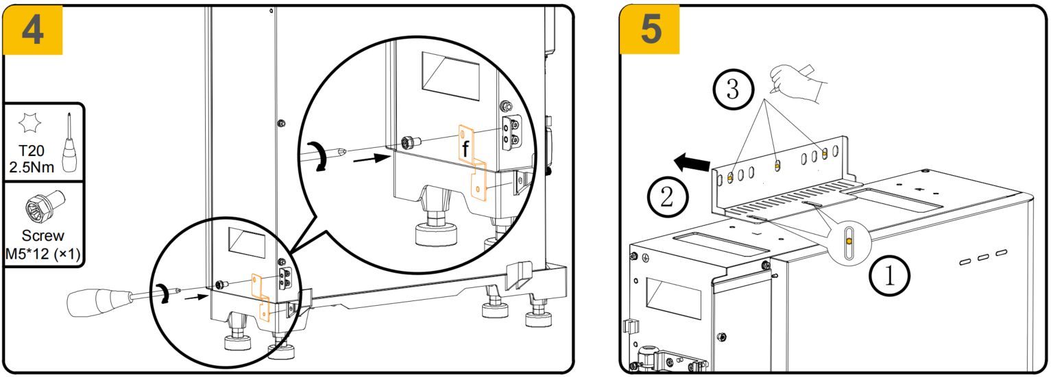
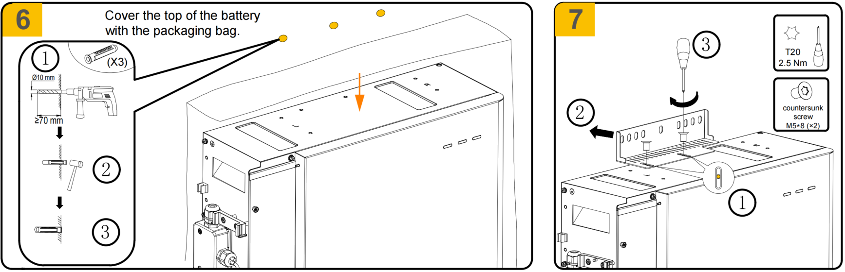
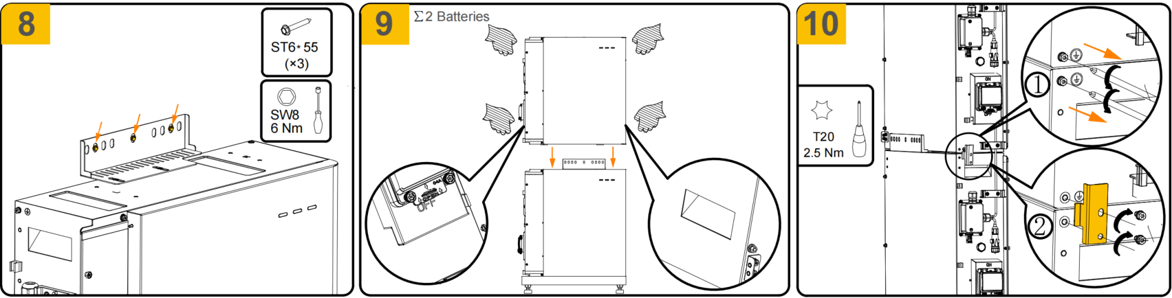
Figure 5-3 Battery Base Installation Steps Diagram
Mounting the Battery without Base Unit
When mounting multiple series batteries with wall brackets for the first time, please follow the below steps.
Take out the limit cardboard, place horizontally against the wall. Refer to 1 in Figure 5-4.
Attach the battery tightly to the limit cardboard. Refer to 2 in Figure 5-4.
Position the wall bracket at the top of the battery, aligning it with the battery's mounting holes. Mark the contact points against the wall using a marker pen. Refer to 3 in Figure 5-4.
Cover the top of the battery with the packaging bag. Using a hammer drill, bore holes along the previously marked positions on the wall. Drive the expansion plugs into the holes using a hammer, then remove the packaging bag. Refer to 4 in Figure 5-4.
Secure the wall bracket and the top of the battery using M5 screws. (tool: T20 screwdriver, torque: 2.5 Nm). Refer to 5 in Figure 5-4.
Screw the ST6 into the expansion nut. (tool: SW8, torque: 6 Nm). Refer to 6 in Figure 5-4.
Place the second battery on top of the first battery, ensuring the battery switch is closed. Refer to 7 in Figure 5-4.
Secure the grounding bar between the two batteries. (tool: T20 screwdriver, torque: 2.5 Nm). Refer to 8 in Figure 5-4.
Repeat steps 3 to 8 to complete the installation of two batteries.
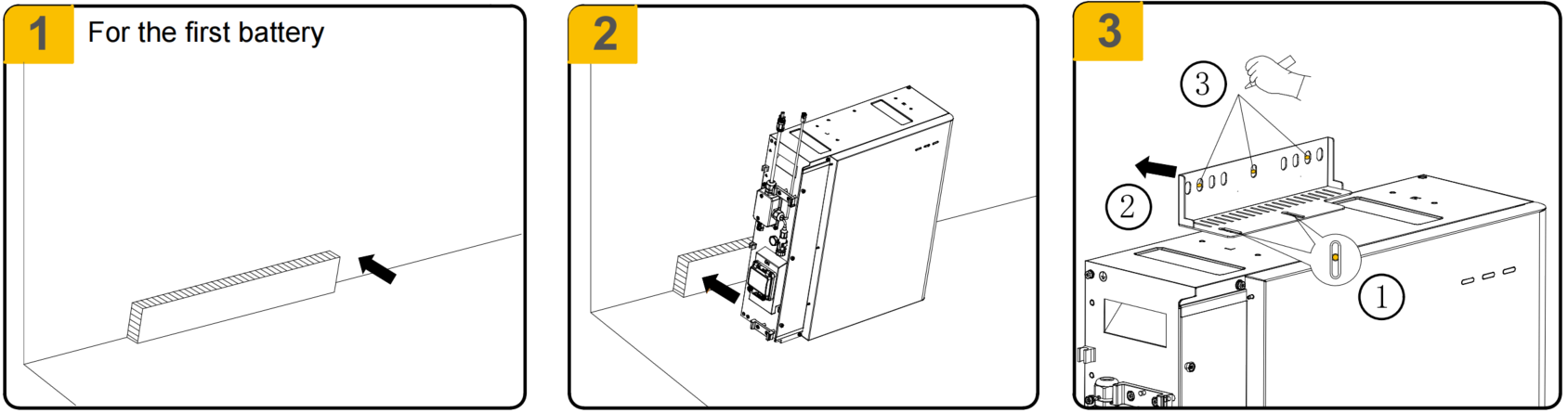
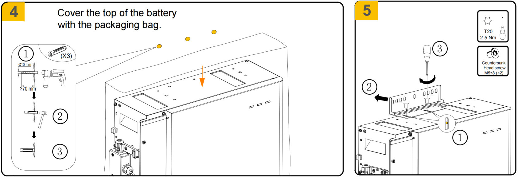
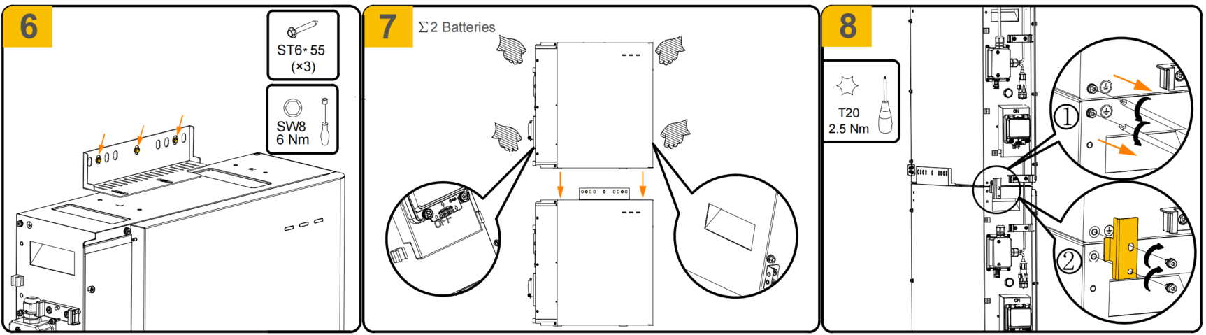
Figure 5‑4 Battery Base Installation Steps Diagram
Mounting the Battery with Wall Bracket
For additional batteries installation, the expansion batteries should be mounted below existing batteries, please follow the below steps.
Select a suitable height for the wall bracket location. Please reserve enough height if you want to add more batteries later.
Mark one drilling position which is used to secure the upper middle location of the wall bracket later and drill the marked hole with a Φ10 drill. Insert the screw anchor into the drill hole, and pre-tighten the wall bracket horizontally with the provided screw (tool: Socket wrench SW8, torque: 4 Nm). Retain 5~10 mm from the screw head to the wall. Refer to Figure 5‑5.
Take out the wall bracket from the packaging and hang the wall bracket on the screw head, adjust its horizontal position, then mark the other drilling positions, drill the marked holes with a Φ10 drill and insert the screw anchors into the drill holes. Refer to 2 in Figure 5‑6.
Secure the wall bracket to the wall (tool: Socket wrench SW8, torque: 6 Nm).Refer to 3 in Figure 5‑6.
Horizontally lift the battery using the handles at two sides and let the top hooks on the back of the battery slide from right to left in the upper beam of the wall bracket. Refer to 4 in Figure 5‑6.
Secure the battery to the wall bracket and tighten them with two M5*12 screws (tool: T20 screwdriver, torque: 2.5 Nm). Refer to 5 in Figure 5‑6.
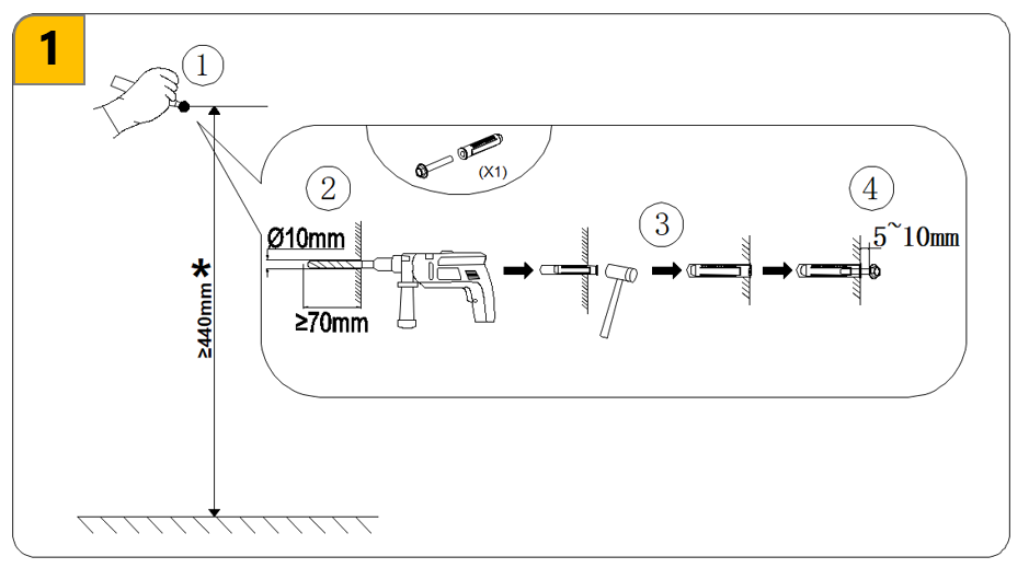
Figure 5‑5 Selection of wall-mounted bracket position
* This recommended value “440 mm” is for wall bracket location of the bottom battery. Depending on the number of expansion batteries mounted later, meanwhile it is advisable to have a minimum of 100 mm off the ground to protect the system from submergence.
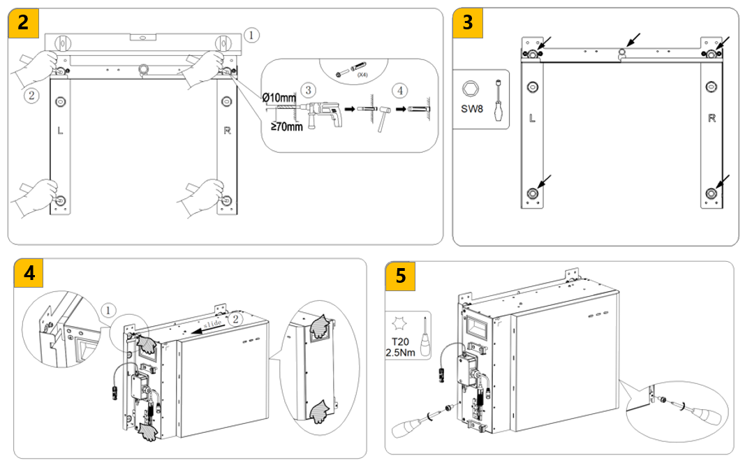
Figure 5‑6 Installation diagram of a single battery wall-mounted bracket
Mounting the top Cover of the Battery(Optional)
Mount the top cover on the battery top, detailed steps as follows:
- Take out the top cover support from the package.
Mount two top cover supports onto the top of the second column battery with four hexagon head screws M5*12 (tool: T20 screwdriver, torque: 2.5 Nm). Refer to 1 in Figure 5-7.
- Take out the top cover from the package.
Mount the top cover onto the top of two top cover supports with four countersunk head screws M4*8 (tool: T20 screwdriver, torque: 1.6 Nm). Refer to 2 in Figure 5-7.
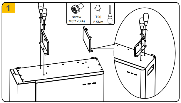
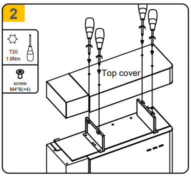
Figure 5-7 Battery top cover installation
Mounting the Inverter
Mount the inverter standing on the battery
Take out the left support foot and right support foot from the inverter packaging.
Mount the left support foot and right support foot onto the top of the upper battery. Refer to 1 in Figure 5‑8.
Place the inverter into the two support feet.
When doing so, the lower right and left holes on the bottom of the inverter must be inserted into the respective guides in the support feet. Refer to 2 in Figure 5‑11.
Attach the inverter to the side support feet. The inverter mounting holes should align to the horizontal holes of the side support feet. Note that the inverter sits inside (between) the two feet and is secured with two screws on the left and right sides. Refer to 3 in Figure 5‑8.
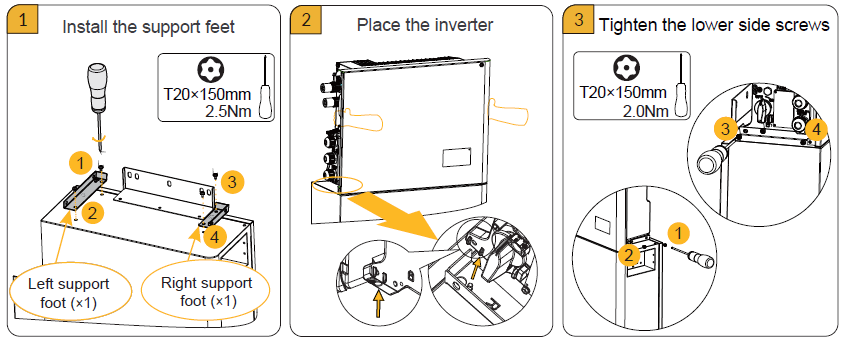
Figure 5-8 Inverter installation diagram
Mount the inverter on the wall using the bracket.
Take out the wall bracket of the energy storage inverter from the packaging.
Choose a suitable height to install the inverter wall mount. Please note that if a battery is to be installed later, the installation space for the battery should also be taken into account.
Use a spirit level to ensure that the wall mount is in a horizontal state. The first step is to mark the hole positions, then remove the wall mount and use a 10mm diameter electric drill to drill holes, and then insert the expansion nuts into the wall. Then place the wall mount in the position that needs to be fixed and fix it with expansion screws (tool: torque wrench SW8, torque 6Nm). Refer to Figure 5‑9 below.
Hook the inverter onto the wall bracket. Refer to 4 in Figure 5‑11.
Secure the inverter to the wall bracket. Insert the hexagon head screws M5*12 into the lower and upper holes on both sides of the inverter respectively and tighten them. Ensure that the inverter is securely in place. Refer to Figure 5‑11.
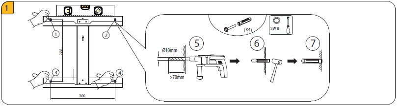
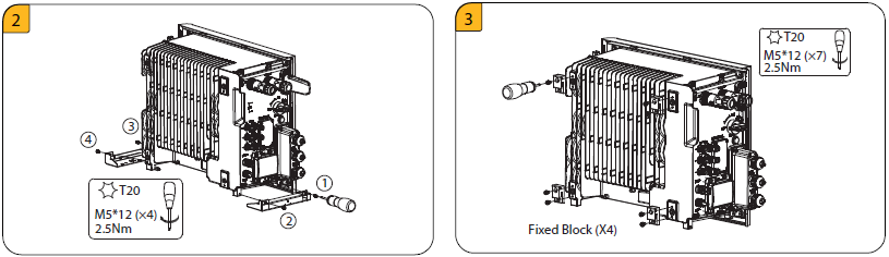
Figure 5-9 Inverter bracket fixation diagram
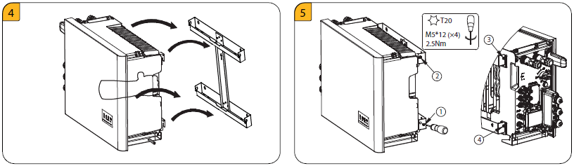
Figure 5-10 Four hooks fixation diagram
Figure 5-11 The inverter is connected to the bracket diagram
Battery Installation for Battery-Ready Application(optional)
Battery Ready scenario is that end users initially only installed ESS inverter as PV inverter but did not install batteries, later the users decide to install the batteries. At this section we will introduce how to mount the first series battery, please follow these steps.
Take out the wall bracket from battery package and two connectors for wall brackets from inverter wall bracket package, assemble them with M5 nuts (tool: Socket wrench SW8, torque: 2.5 Nm). Refer to 1 in Figure 5‑12.
Align the upper holes of the two connectors for battery wall bracket to the lower rivets of the wall bracket of the hybrid inverter, mark the drilling position of the newly wall bracket of the series battery. Refer to 2-3 in Figure 5‑12.
Remove the newly assembled battery wall bracket, drill the marked hole with drill Φ10. Insert screw anchors into the drilling holes, tighten the screws with the SW8 socket wrench to secure the wall bracket to the wall. Refer to 4-6 in Figure 5‑12.
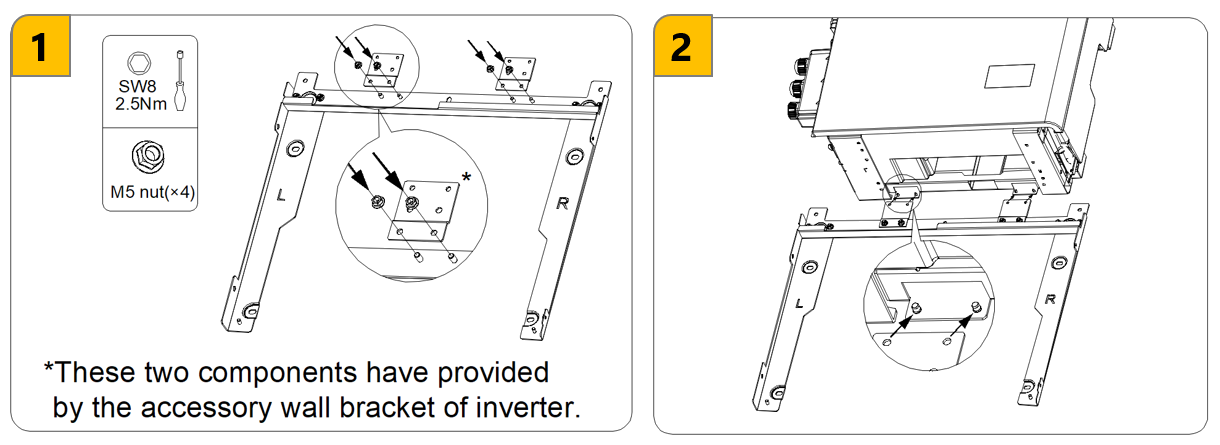
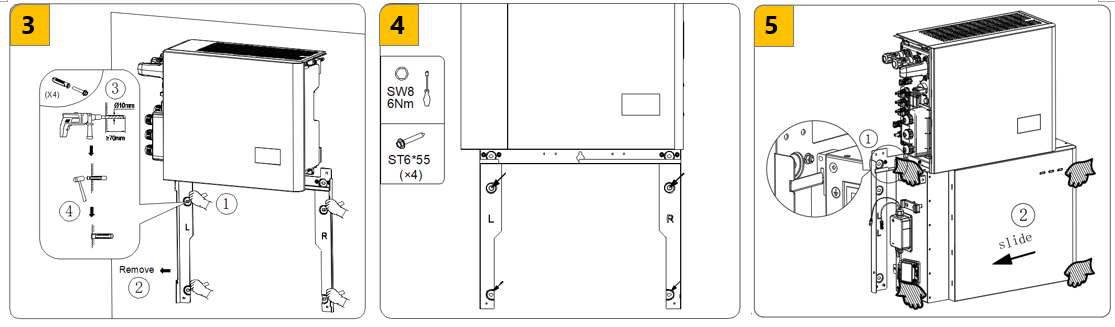
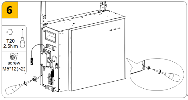
Figure 5-12 the first series battery installation
Mounting the Wi-Fi Dongle
Mount the Wi-Fi dongle at the left of the inverter, detailed steps as follows:
- Remove the protective cover of Wi-Fi port at the left of the inverter.
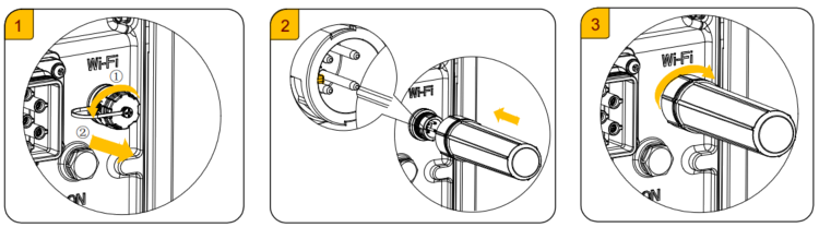
Figure 5-13 Installation diagram of Wi-Fi Dongle
- Rotate the Wi-Fi Dongle onto the inverter.