

Electrical Connection
Precautions
DANGER
Electric Shock Hazard - Before connecting cables, switch off all circuit breakers and switches connected to the inverter and batteries.
WARNING
- Damage to the energy storage system caused by incorrect cable connections is not covered under warranty.
- Only certified electricians accredited by AlphaESS are allowed to connect cables.
- Appropriate PPE must be worn when installing or connecting the product.
INFO
The cable colors shown in the electrical connection diagrams provided in this
chapter are for reference only.
Select cables in accordance with local cable specifications (green-and-yellow
cables are only used for PE).
Cable Requirements for Connection
|
|
|
|
|
|
1 | PV Power cable | Standard PV cable (recommended type: H1Z2Z2-K) | 4~6mm2 | 5.5~ 9mm | Purchased by the installer |
2* | Signal cable | Standard network cable (recommended type: Cat5e, SFTP, UV-resistant for outdoor use) | 0.12~0.2mm2 (AWG26~AWG24) | 4~6mm | Purchased by the installer |
3** | Signal cable | Two-core outdoor shielded twisted pair copper cable | 0.5~1.5mm2 | 4~6mm | Purchased by the installer |
4*** | Signal cable | Outdoor shielded twisted pair copper cable | 0.5~1.3mm2 | 4~6mm | Purchased by the installer |
5 | AC power cable | Five-core (L1, L3, L3, N and PE) outdoor copper cable | 4~6mm2 | 13 ~17.5mm | Purchased by the installer |
6 | PE cable | Single-core outdoor copper cable | 2.5~6mm2 | N/A | Purchased by the installer |
* For RS485, LAN, three-phase meter (with CT), DRM&RRCR communication connection with inverter.
** For three-phase meter (without CT) communication connection with inverter.
*** For AUX communication connection with inverter.
Grounding Connection
WARNING
Electric Shock Hazard
Before doing electrical connection, please ensure the PV switch & all AC and BAT circuit breakers in the energy storage system are switched OFF and cannot be accidentally or unintentionally reactivated.
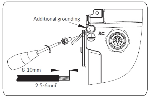
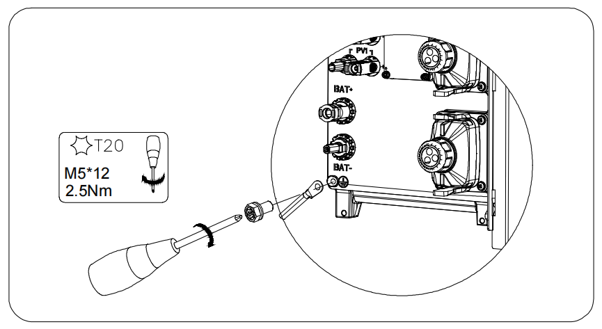
A grounding point is provided near the grid connector of the energy storage inverter.Take out M5 Y terminals, strip the grounding cable insulation, insert the stripped conductor into the ring terminal lug and crimp with a crimping tool.Connect the grounding terminal to the inverter (tool: T20 screwdriver, torque: 2.5Nm).
Grounding connection for the energy storage inverter.
Grounding connection between the energy storage inverter and series battery.
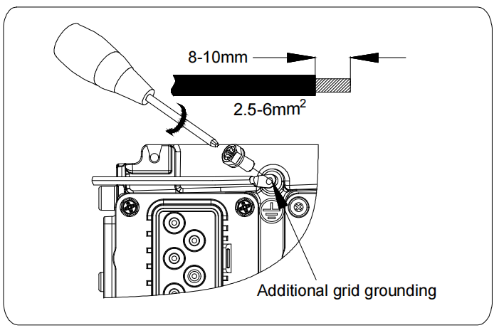
Inverter side Series Battery side
AC Connection
Requirements for the AC Connection
AC cable requirements as follows:1. Conductor type: copper conductor (tinned copper preferred).2. Grid cable current carrying capacity depends on the inverter model selected and max. full current from grid, example for 10kW inverter model, max. current: 21.7A.
- Backup cable current carrying capacity depends on the inverter model selected and loads connected when the mains grid is available, example for 10kW inverter model, max. current: 21.7A.
Note: Account for temperature derating and voltage drop/rise when selecting wire diameters. 110°C or higher rated cable derates slower as temperatures increase.
External diameter: usually 13 mm to 17.5 mm for grid connector and backup connector
Grid and backup conductor cross-section recommendation: 4-6 mm².
Insulation stripping length: 10 mm.
Sheath stripping length: 43 mm.
DANGER
You must protect each inverter with an individual grid/backup circuit breaker in order to ensure that the inverter can be disconnected safely.
WARNING
Residual-current monitoring unit
The inverter does not require an external residual-current device when operating.
If local regulations or a particular installation configuration requires the use of a residual-current device, or a Hybrid-coupled storage system with a big coupling capacity from the PV array and PV inverter, the following must be observed:
The inverter is compatible with type A residual-current devices with a rated residual current of 100mA or higher. Each inverter in the system must be connected to the utility grid via a separate residual-current device.
WARNING
For Australia and New Zealand installation sites, the neutral cables of grid side and backup side must be connected together, otherwise the backup output function will not work normally.
Selecting Suitable AC Circuit Breaker
The general requirements for the selection of circuit breakers are determined by standards and country-specific provisions. The following factors should be considered when selecting a suitable circuit breaker:
Factors influencing the current-carrying capacity of the cable: type of cable used, ambient temperature around the cable, type of cable routing, bundling of cables.
Other influencing factors: loop impedance, mutual heating of circuit breakers, ambient temperature at the circuit breaker, selectivity, type of connected device.
If these factors are ignored, it will increase the risk of the circuit breaker tripping under normal operating conditions.
Selecting Circuit Breakers for the AC supply and Backup output is dependent on the maximum current of the backup circuit and the inverter (if it is force-charged), the model of MCBs used and their derating current rating considering their maximum temperatures. Supplier Datasheets detail temperature derating for their MCBs. Ensure the MCBs used are appropriate for the current and the operating temperature. Otherwise, the risk of the circuit breaker tripping will increase under normal operating conditions.
AC connection recommendation for SMILE-G3-T4-INV
| Description | Max. Current | Breaker Type | Recommended Cable Cross Section |
| Grid Side | 11.6 A | 16 A | 2.5~6 mm2 |
| Backup Side | 8.7 A | 16 A | 2.5~6 mm2 |
AC connection recommendation for SMILE-G3-T5-INV
| Description | Max. Current | Breaker Type | Recommended Cable Cross Section |
| Grid Side | 14.5 A | 25 A | 4~6 mm2 |
| Backup Side | 10.9 A | 16 A | 2.5~6 mm2 |
AC connection recommendation for SMILE-G3-T6-INV
| Description | Max. Current | Breaker Type | Recommended Cable Cross Section |
| Grid Side | 17.4 A | 25 A | 4~6 mm2 |
| Backup Side | 13 A | 20 A | 4~6 mm2 |
AC connection recommendation for SMILE-G3-T8-INV
| Description | Max. Current | Breaker Type | Recommended Cable Cross Section |
| Grid Side | 17.4 A | 25 A | 4~6 mm2 |
| Backup Side | 13 A | 20 A | 4~6 mm2 |
AC connection recommendation for SMILE-G3-T10-INV
| Description | Max. Current | Breaker Type | Recommended Cable Cross Section |
| Grid Side | 21.7 A | 32 A | 4~6 mm2 |
| Backup Side | 21.7 A | 32 A | 4~6 mm2 |
AC connection recommendation for SMILE-G3-T12-INV
| Description | Max. current | Breaker type | Recommend cable cross section |
| Grid Side | 24.6 A | 40 A | 6~10 mm2 |
| Backup Side | 19.1 A | 32 A | 6~10 mm2 |
AC connection recommendation for SMILE-G3-T15-INV
| Description | Max. current | Breaker type | Recommend cable cross section |
| Grid Side | 29 A | 50 A | 6~10 mm2 |
| Backup Side | 23.9 A | 40 A | 6~10 mm2 |
Grid and Backup Connection
WARNING
Use AlphaESS App or AlphaCloud to select the current rating of the circuit breaker used to protect the AC cable connecting to the inverter
The BESS is programmed to limit the battery charge rate (from the grid) depending on the backup circuit current and the size of the MCB used. This avoids the risk of the backup circuit combining with a force-charge or VPP charge and pulling too much current through the grid-supply AC cable/MCB.
Note that an Automatic Transfer Switch can be used to bypass the battery AC cable and backup connection if preferred. In this case, the current on the Backup Output plug will be 0A until there is a power outage. This means that the MCB on the AC supply to the battery only needs to be sized for the maximum current rating of the inverter (i. e. 21.7 A for a 5kW inverter).
The combined current of the Battery Grid-charge and the backup circuit will be limited to the current rating of the MCB less 2 A (to account for the temperature derating of a typical MCB). Installers must advise AlphaESS if the MCB used has a steeper derating factor where the 2A buffer would not be sufficient.
Example: If a 32A MCB is used and the backup circuit is drawing 15 A, any force charging of the battery will be limited to (32 A-2 A) – 15 A = 15 A. If the load on the backup circuits drops to 11 A, the maximum grid-charge current would increase to 19 A.
Where the wire diameter used for the AC connection to or from the battery inverter exceeds the maximum wire diameter for the grid connector plug below (e. g. if a long cable run is required and Voltage Rise Calculations require a wire of greater than 10 mm2), use an intermediary connection point close to the battery to downsize the wire. Ensure that the short-run wire type is appropriate for the current and temperature (e. g. 180 °C Silicone flex will carry much greater current than vs 90 °C PVC) and use an intermediate MCB at the intermediary connection point if required.
The steps for connecting the grid connector are as follows:
1. Disconnect the PV switch, grid, backup and battery circuit breaker and secure them to prevent reconnection.2. Strip the AC cable outer insulation by 43 mm.3. Shorten L1, L2, L3 and N by 3 mm each, so that the grounding conductor is 3 mm longer. This ensures that the grounding conductor is the last to be pulled from the screw terminal in the event of tensile strain.4. Strip the insulation of L1, L2, L3, N and the grounding conductor 10 mm.5. If using fine stranded wire, fit L1, L2, L3, N and PE with bootlace ferrules.6. Disassemble the grid connector plug, pass the swivel nut and threaded sleeve over the AC cable.
7. Insert the five conductors into the screw terminals on the bush insert and tighten the screws using the torque 1.2 Nm with provided tool. Ensure that all conductors are securely fastened in the screw terminals on the bush insert.
8. Insert the threaded sleeve into the bush insert and hear the "click" sound. Screw the swivel nut onto the threaded sleeve.
9. Insert the grid plug connector into the grid connection socket for the grid connection until it audibly snaps into place. When doing so, align the grid plug connector so that the convex rib on the bush insert of the grid plug connector should point to the groove on the grid connection socket first, and then insert the grid plug connector to the grid connection socket.
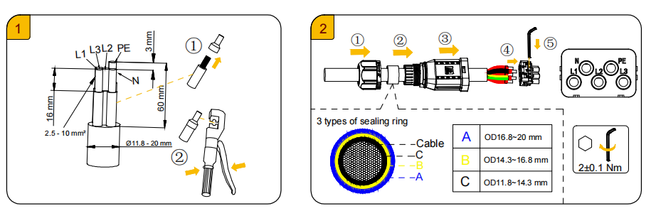
Figure 6-1 Grid connection steps diagram
The steps for backup connection are similar to the grid connection, with a distinction in step 9:
Insert the backup plug connector into the backup connection socket for the backup connection until it audibly snaps into place. When doing so, align the backup plug connector so that the groove on the bush insert of the backup plug connector should point to the convex rib on the backup connection socket first, and then insert the backup plug connector to the backup connection socket.
Disassembling Grid and Backup Connectors
Disassemble the grid plug connector (e.g. due to faulty assembly), proceed as follows.
1. Unplug the grid plug connector. Detailed steps: use a flat-blade screwdriver (blade width: 2.5 mm) to push the orange latch forwards to unlock the connector coupling structure, rotate the bush insert of the grid plug connector anticlockwise, then pull the grid plug connector apart from the grid connection socket. Do not pull on the cable.
2. Unlock the grid plug connector. To do this, unscrew the swivel nut from the threaded sleeve, then insert a flat-blade screwdriver (blade width: 2.5 mm) into the side catch mechanism and pry the catch mechanism open. Carefully pull the bush insert apart.
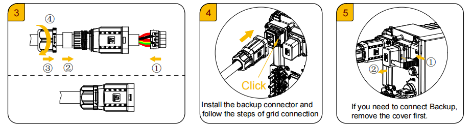
Figure 6-2 Backup connector installation
Disassemble the backup plug connector (e.g. due to faulty assembly), proceed as follows.
1. Unplug the backup plug connector. Detailed steps: use a flat-blade screwdriver (blade width: 2.5 mm) to push the orange latch forwards to unlock the connector coupling structure, rotate the bush insert of the backup plug connector clockwise, then pull the backup plug connector apart from the backup connection socket. Do not pull on the cable.
2. Unlock the backup plug connector. To do this, unscrew the swivel nut from the threaded sleeve, then insert a flat-blade screwdriver (blade width: 2.5 mm) into the side catch mechanism and pry the catch mechanism open. Carefully pull the bush insert apart.
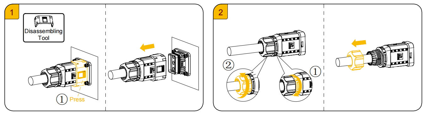
Figure 6-3 Disassembly of the Backup connector
Meter Connection
| Item | Scenarios |
| DTSU666-3*230V 5(80)A | Three-phase meter (without CT) |
| DTSU666-3*230V 100A/40mA | Three-phase meter (with CT) |
| DTSU666-3*230V 250A/50mA | Three-phase meter (with CT) |
| SMILE-TLMeter-CH3C60/100/250/400 (Single-Circuit) | Single phase wireless meter(1CT) |
| SMILE-TLMeter-CH6C60/100/250/400 (Dual-Circuit) | Single phase wireless meter(2CT) |
Loosen the strain relief nuts of the cable glands on the COM connection cover of inverter, and unscrew the 4 screws on the corners, then you will see meter communication ports.
Any of the meter communication ports can be used.
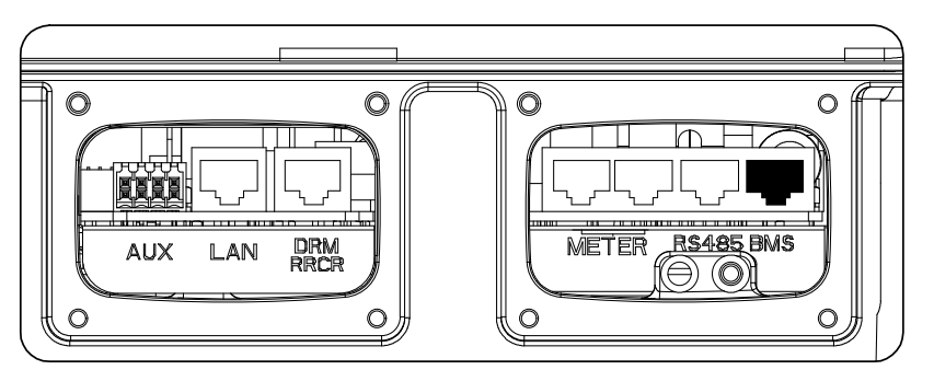
Figure 6-4 Electric meter connection
Meter Wiring
Pass the meter communication cable through the cable gland of the COM connection cover but don’t tighten the strain relief nut of the cable gland.
Insert the RJ45 plug of the meter communication cable into the METER communication port labelled “METER” of the inverter.
The other steps for meter connection as follows:
- DTSU666-3*230V 5(80)A: Three phase meter (without CT) connection
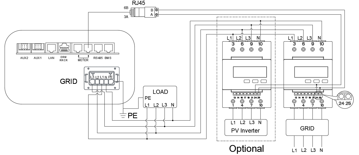
Figure 6-5 Wiring at three-phase feed in
Meter communication cable requirements: two-core outdoor shielded twisted pair copper cable (flexible), conductor cross-section 0.5~1.5mm2, wires terminal should be fitted with bootlace ferrules.
- DTSU666-3*230V 100A/40mA, DTSU666-3*230V 250A/50mA: Three phase meter (with CT) connection
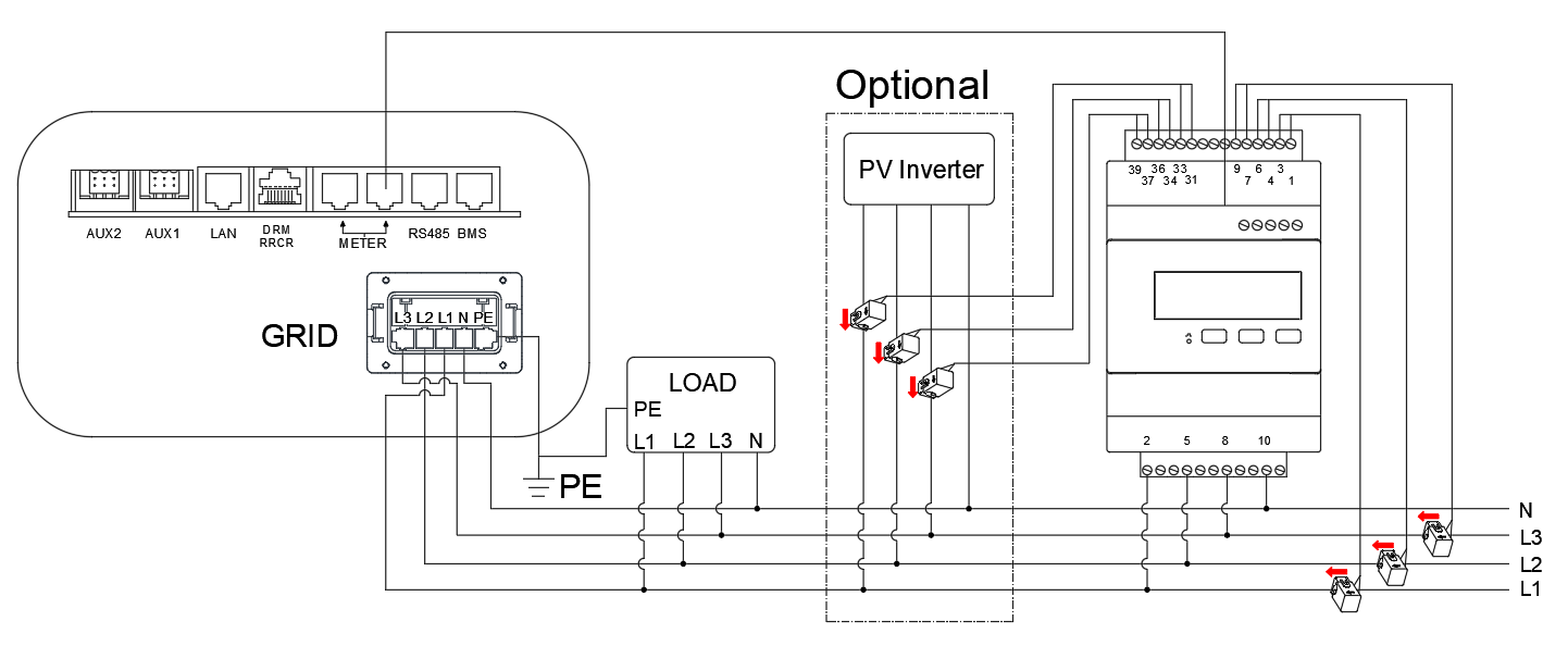
Figure 6-6 Wiring at three-phase feed in
Meter communication cable requirements: standard network cable (recommended type: Cat5e, SFTP, UV-resistant for outdoor use).
The connections are marked clearly on the meter.
Wiring location description of Chint three phase meter (with CT)
| Grid CT | PV CT | GRID |
| 1--------IA* (White) | 31--------IA* (White) | 2----------L1 |
| 3--------IA (Blue) | 33--------IA (Blue) | 5----------L2 |
| 4--------IB* (White) | 34--------IB* (White) | 8----------L3 |
| 6--------IB (Blue) | 36--------IB (Blue) | 10-------- N |
| 7--------IC* (White) | 37--------IC* (White) | |
| 9--------IC (Blue) | 39--------IC (Blue) |

3. SMILE-TLMeter-CH3C60/100/250 (Single-Circuit) :Three-phase single-circuit meter
(1 CT) connection
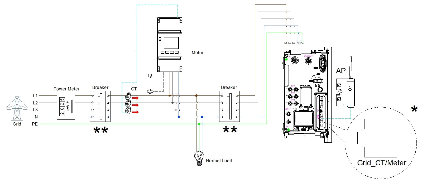
Figure 6-7 Wiring at three-phase feed in
4. SMILE-TLMeter-CH6C60/100/250 (Dual-Circuit) :Three-phase dual-circuit meter (2
CT)connection
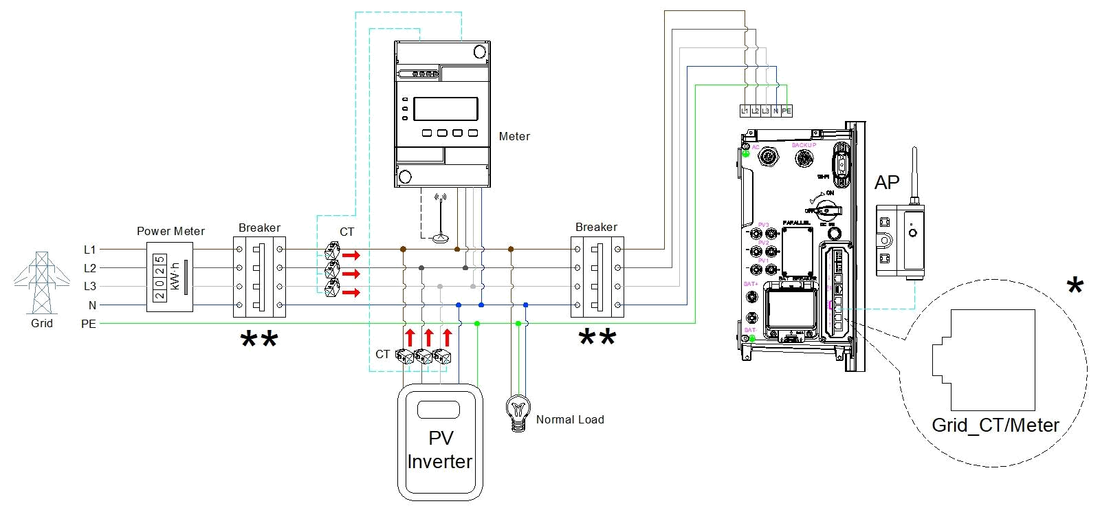
Figure 6-8 Wiring at three-phase feed in
* When used with the G3-T5/T10 series, the AP module is connected to the
'Grid_CT/METER' port.
** In Australia and New Zealand, the N wire does not need to be connected to a circuit
breaker.
INFO
Be VERY careful when wiring or checking these connections because the connections appear reversed when the meter is secured in place on the Din Rail. Always physically check the label on the meter when wiring any CTs or grid reference wires.
Meter Configuration
Meter Setting on the Meter’s Display
If connecting Chint DTSU666 meters without CTs, two meters are required if there is any AC-coupled PV inverter, one for the Grid Import/Export and one for the AC-coupled PV inverter measurements.
| Model | Grid Meter Address | PV Meter Address |
| DTSU666-3*230V 5(80)A (without CT) | 1 | 2 |
| DTSU666-3*230V 100A/40mA (with CT) | 1 | N/A |
| DTSU666-3*230V 250A/50mA (with CT) | 1 | N/A |
1. Meter setting for type DTSU666-3*230V 5(80)A, which is three-phase meter (without CT)
When the meter is used as grid meter, the default address is 1. The installer doesn't need to make any other settings.
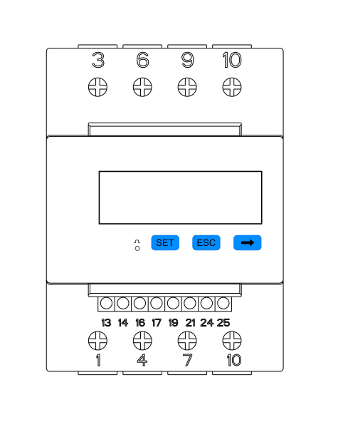
Figure 6-9 DTSU666-3*230V 5 (80) A type three-phase electricity meter (without CT) setting
If installer wants to have a check, please follow the steps below:
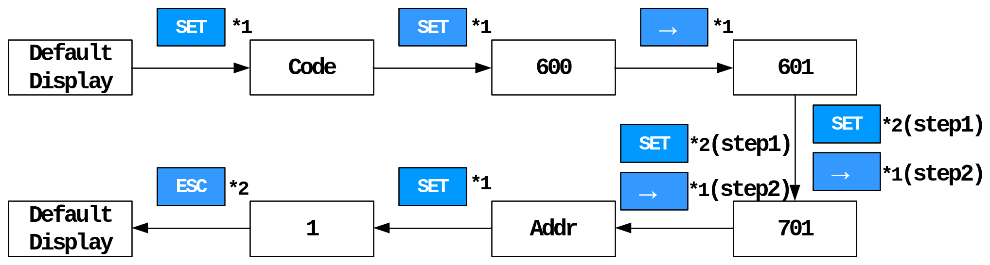
Figure 6-10 Installation program check
When the meter is used as PV meter, please follow the steps below to complete the address setting:
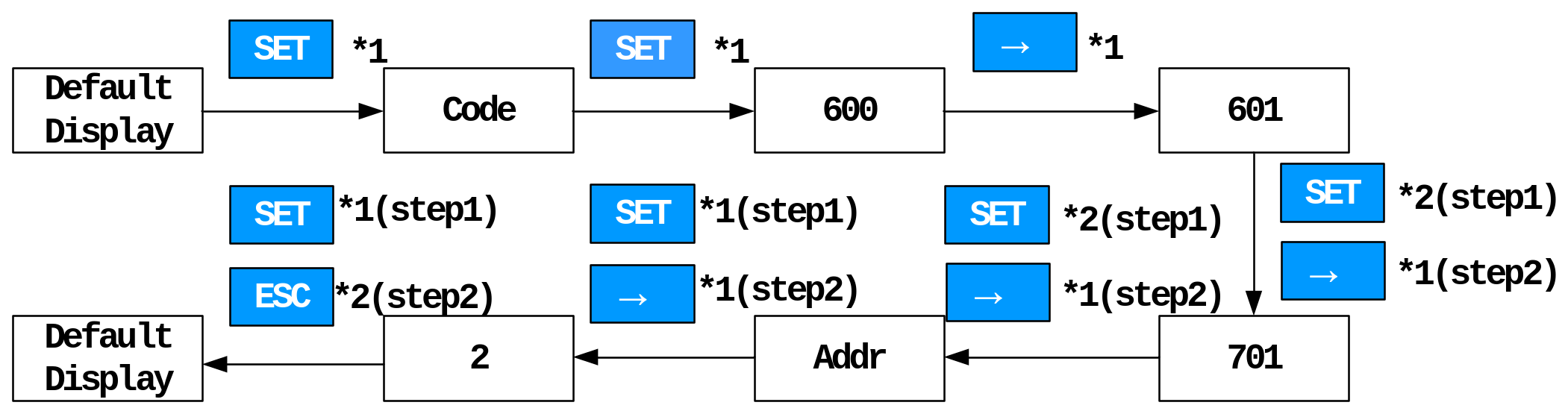
Figure 6-11 Address setting for photovoltaic electricity meters
2. Meter setting for type DTSU666-3*230V 100A/40mA and DTSU666-3*230V 250A/50mA, three-phase meter (with CT)
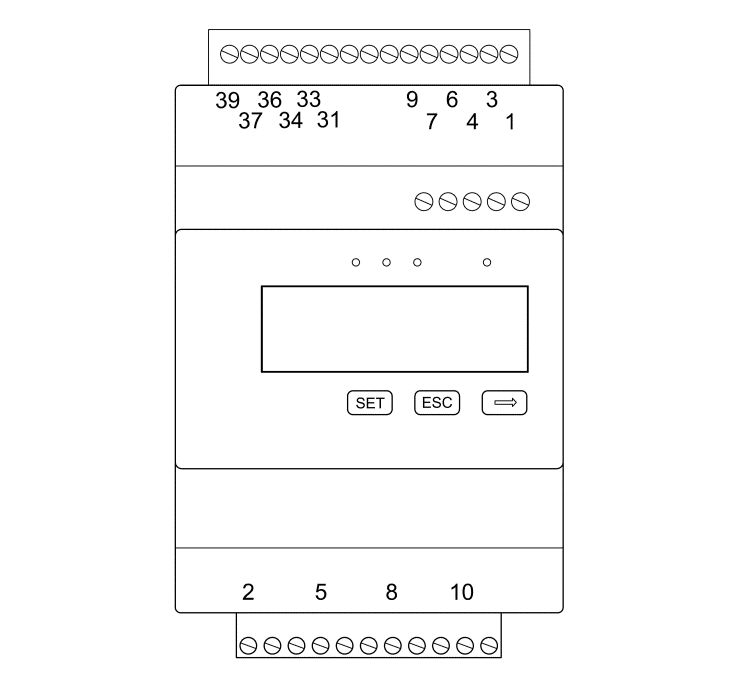
Figure 6-12 Range setting of DTSU666-3*230V 100A/40mA three-phase electricity meter (with CT)
The default address is 1. The installer doesn't need to make any other settings.
If installer wants to have a check, please follow the steps below:
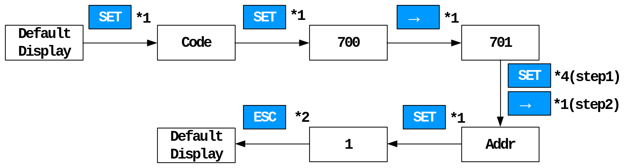
Figure 6-13 Installation program check
The display order of parameters:
The following images show the information read and displayed by the meter in real time.
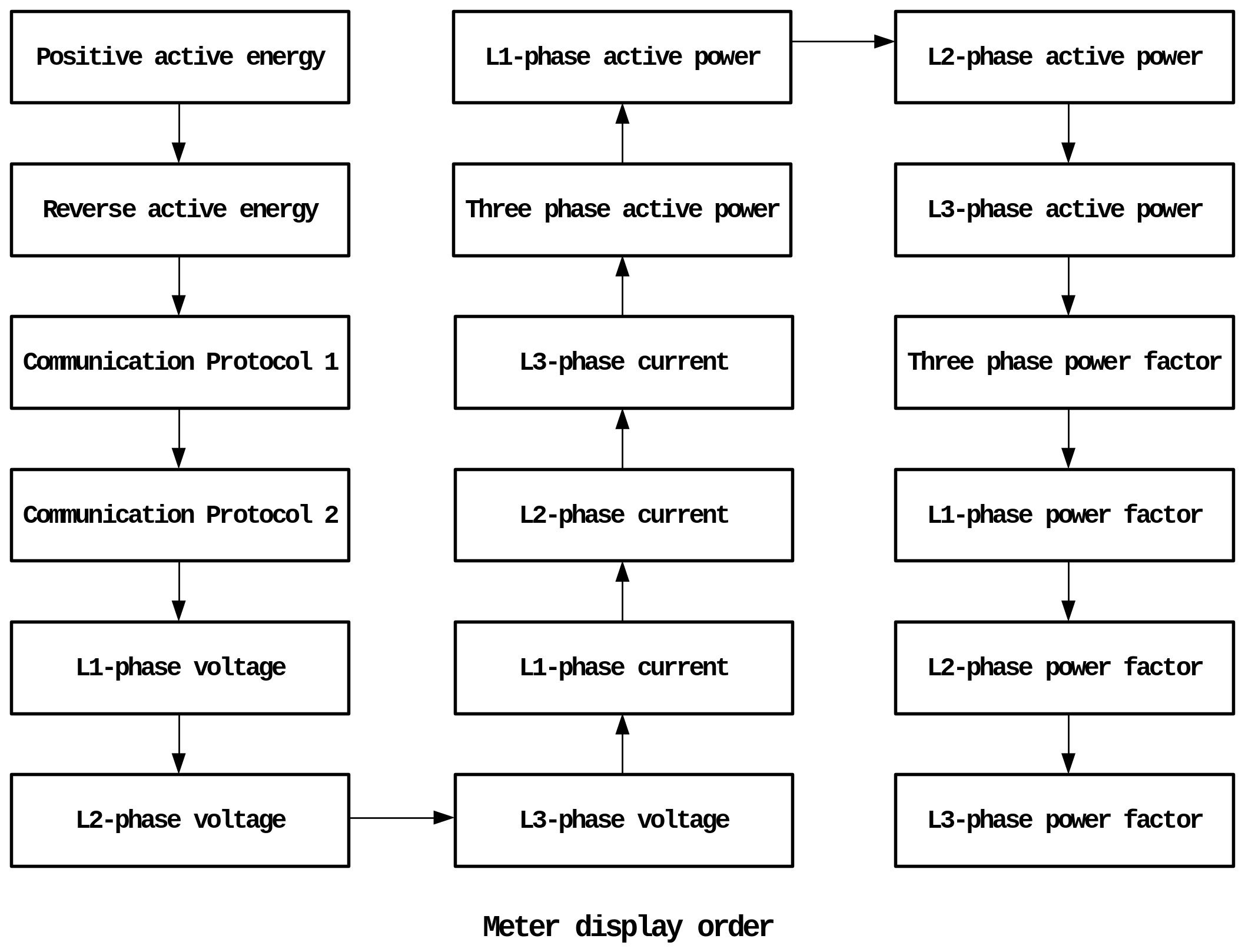
Figure 6-14 Parameter display sequence
Meter setting for type SMILE-TLMeter-CH3C60/100/250/400 (Single-Circuit) is the same as DTSU666-3*230V 5(80)A.
Meter setting for type SMILE-TLMeter-CH6C60/100/250/400 (Dual-Circuit) is the same as DTSU666-3*230V 100A/40mA.
PV Connection
Connecting the PV Array
DANGER
Danger to life due to electric shock if live components or DC cables are touched
The DC cables connected to a battery or a PV module may be live. Touching live DC cables can result in serious injury or even death due to electric shock. To avoid this danger:
- Disconnect the inverter and battery from voltage sources and make sure it cannot be reconnected before working on the device.
- Do not touch non-insulated parts or cables.
- Do not disconnect the DC connectors under load.
- Wear suitable personal protective equipment for all work on the product.
- Observe all safety information in this document.
INFO
Risk of the inverter due to overvoltage
The inverter can be destroyed if the open-circuit voltage of the PV modules exceeds the maximum input voltage of the inverter.
- If the open-circuit voltage of the PV modules exceeds the maximum input voltage of the inverter, do not connect any strings to the inverter and check the design of the PV system.
INFO
Risk of product damage due to ground fault on DC side during operation
Due to the transformerless topology of the inverter, ground faults on DC side during operation can lead to irreparable damage. Damages to the inverter due to a faulty or damaged DC installation are not covered by warranty. Although the inverter is equipped with a protective device that checks whether a ground fault is present during the starting sequence, the inverter is not protected during operation.
- Ensure that the DC installation is carried out correctly and no ground fault occurs during operation.
INFO
Risk of the inverter damage due to sand, dust and moisture ingress if the PV
inputs are not closed
The inverter is properly sealed only when all unused PV inputs are closed with sealing plugs. Sand, dust and moisture penetration can damage the inverter and impair its functionality.
- Seal all unused PV inputs with sealing plugs.
Please ensure the follows before connecting PV strings to the inverter:
Make sure the open voltage of the PV strings will not exceed the max. DC input voltage (1100Vdc). Violating this condition will void the warranty.
Make sure the polarity of the PV connectors is correct.
Make sure the PV-switch, circuit breakers of battery, AC-BACKUP and AC-Grid are all isolated/in their “off” states.
Make sure the PV resistor to ground is higher than 200K Ohms.
The inverter uses the Vaconn D4 PV connectors. Please follow the picture below to assemble the PV connectors. PV conductor cross section requirements: 4~6 mm2.
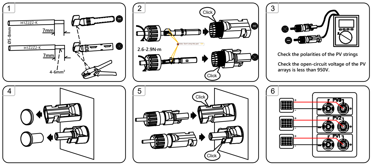
Figure 6-15 Assembly of photovoltaic connectors
Disassembling the PV Connector
DANGER
Danger to life due to electric shock if live components or DC cables are touched
The DC cables connected to a PV module may be live. Touching live DC cables can result in serious injury or even death due to electric shock. To avoid this danger:
Disconnect the inverter and battery from voltage sources and make sure it cannot be reconnected before working on the device.
Do not touch non-insulated parts or cables.
Do not disconnect the DC connectors under load.
Wear suitable personal protective equipment for all work on the product.
Observe all safety information in this document.
Ensure that the PV connector can only be removed via using the Connector removal wrench.
Removing the PV connector without the PV Connector Disassembling Tool isn’t allowed and dangerous.
- Release and remove the PV connectors. To do so, insert the removal wrench into the bayonet, press the wrench with an appropriate strength to release the locking mechanism, then pull the PV connectors out. Please do not pull on the cable.
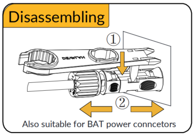
Figure 6-16 Disassembly of PV connectors
- If there are PV connectors unused, please use the PV covers to seal the PV connectors.
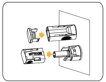
Figure 6-17 Seal the PV connectors
Electrical Connection between the ESS Inverter and Battery
Communication Connection between INV and BAT
Communication cable connection between the inverter and battery proceed as follows.
Take out the battery communication cable from the battery packaging.
Pass the battery communication cable (BMS cable) through the cable gland of the COM connection cover of energy storage inverter. Do not tighten the strain relief nuts of the cable glands yet.
Insert the RJ45 plug into the BMS communication port on the Inverter Communication ports labelled “BMS”.
Only secure the COM connection cover in place after the Meter communication cable, the BMS cable and the LAN cable (if used) have been clipped into their respective ports.
When securing the COM connection cover over the communication ports, tighten the cover in place and then lightly push the communication cables into the cover as you tighten the strain relief nuts onto the cables. This will ensure the communication cables are well-seated in the RJ45 ports.
System Connection between INV and BAT
DANGER
Danger to life due to burns caused by electric arcs through short-circuit currents
Short-circuit currents in the battery can cause heat build-up and electric arcs. Heat build-up and electric arcs may result in lethal injuries due to burns.
Disconnect the battery from all voltages sources prior to performing any work on the battery.
The upper power connector of the lower battery must connect to the lower power connector of the upper battery, otherwise the short-circuiting of the battery will occur.
Please connect both ends of one battery power cable completely before starting to connect the next power cable.
Observe battery safety information provided in the manual.
Detailed electrical connection between the inverter and series batteries as follows:
Take out all cables from the inverter packaging.
Remove the protective caps from the battery power connectors of the inverter and all series batteries.
Complete the grounding, power and communication connection between the upper and lower series batteries.Connect the upper power connector of the lower series battery to the lower power connector of the upper series battery. Connect the upper communication connector of the lower series battery to the lower communication connector of the upper series battery.
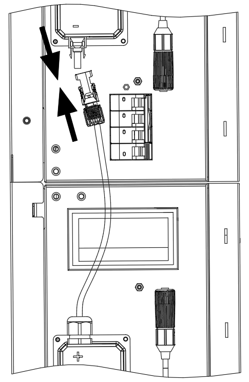
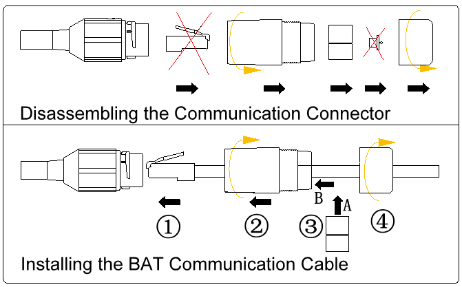
Figure 6-18 Installation of battery connection cables
Use the provided grounding cable to connect the grounding point of the inverter and the grounding point of the top battery.
Take out the red power cable, connect BAT main positive of series batteries (directly below the inverter) to the BAT positive connector of inverter.
Take out the black power cable, connect BAT main negative of series batteries (the last series battery) to the BAT negative connector of inverter.
Cables connection between the Inverter and series batteries of two column.
Cables for distanced horizontal series batteries expansion should be purchased additionally.
Please pay attention to the cable type. There are three kinds of cables:
No. | Picture | Description |
1 |
| The main negative power cable (black) of the system (3m): Connect BAT main negative of series battery and the BAT negative of inverter |
2 |
| The power cable between different column series battery (3m): Connect BAT negative of the bottom battery of first column series battery and BAT positive of the top battery of second column series battery |
3 |
| The battery communication cable (3m): Connect the lower communication connector of the bottom battery of first column series battery and the upper communication connector of the top battery of second column series battery |
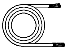
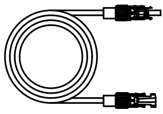
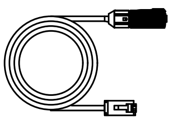
Detailed electrical connection between the inverter and the second series batteries as follows:
Disconnect the energy storage system from all voltages sources prior to performing any work on the system.
Installer should prepare the grounding cable to connect the grounding points between the two column series battery.Take out M5 Y terminals and grounding conductor, strip the insulation of the grounding conductor, insert the stripped conductor into the terminal lug and crimp with a crimping tool.
Complete the electrical connection between two column series batteries.
Use the provided power cable to connect BAT negative connector of the bottom battery of first column series batteries and BAT positive connector of the top battery of second column series batteries.
Use the provided communication cable to connect the lower communication connector of the bottom battery of first column series batteries and the upper communication connector of the top battery of second column series batteries.
Use the assembled grounding cable to connect the grounding point of the bottom battery of first column series batteries and the grounding point of the bottom or top battery of second column series batteries.
Please remove or disassemble the original main negative power cable (2m) provided in the inverter packaging.
Take out the main negative power cable (3m) from accessory of Cables for Distanced Horizontal Battery Expansion, connect BAT main negative of series batteries (the last series battery) to the BAT negative connector of inverter.
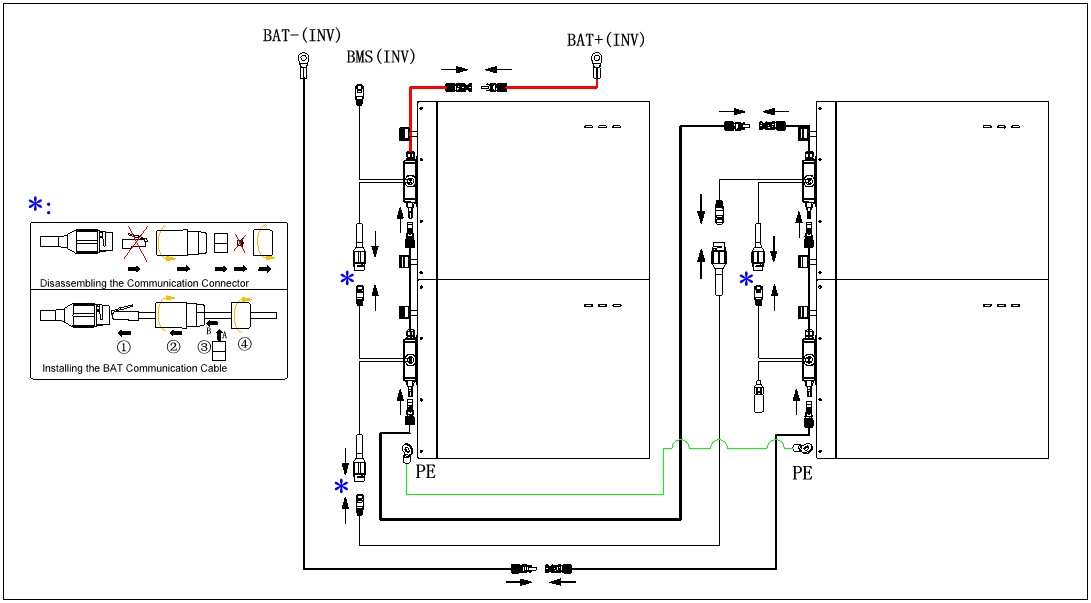
Figure 6-19 Separate series batteries side wiring diagrams
Disassembling BAT Connectors
DANGER
Danger to life due to electric shock when touching exposed DC conductors or
BAT plug contacts if the BAT connectors are damaged or loose
The BAT connectors can break or become damaged, become free of the DC cables, or no longer be connected correctly if the BAT connectors are released and disconnected incorrectly. This can result in the DC conductors or BAT plug contacts being exposed. Touching live DC conductors or BAT plug connectors will result in serious injury or even death due to electric shock.
- Do not disconnect the BAT connectors under load.
- Before removing the BAT connectors, ensure that the BAT circuit breakers of the battery and inverter are OFF.• Wear insulated gloves and use insulated tools when working on the BAT connectors.
- Ensure that the BAT connectors are in perfect condition and that none of the DC conductors or BAT plug contacts are exposed.
- Carefully release and remove the BAT connectors as described in the following.
Ensure that the BAT connector can only be removed via using the removal wrench.
Removing the BAT connector without the removal wrench isn’t allowed and dangerous.
Procedure:1. Release and remove the BAT connectors. To do so, insert the removal wrench into the bayonet, press the wrench with an appropriate strength to release the locking mechanism, then pull the BAT connectors out. Please do not pull on the cable.
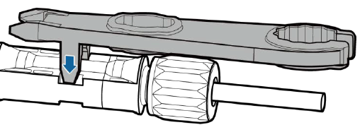
Figure 6-20 Disassemble the BAT connectors
Communication Connection with Inverter
For other communication (AUX,, LAN, RRCR, DRM, Meter, RS485) connection, please follow the steps below.
1. Unscrew the 4 screws on the COM connection cover of the inverter, then loosen the strain relief nuts of the cable glands on the COM connection cover.
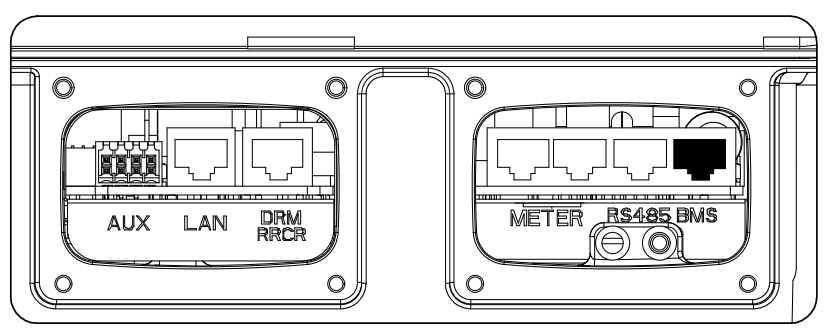
Figure 6-21 COM connection cover
2. Pass the communication cables through the cable glands of the COM connection cover. Do not tighten the strain relief nuts of the cable glands yet.
Insert the RJ45 plugs to the relative RJ45 sockets.
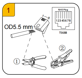
Figure 6-22 RJ45 plug connection
For meter wiring, please refer to Chapter 6.3.5.1 for Meter Wiring.
If DRM support is specified, the system may only be used in conjunction with a Demand Response Enabling Device (DRED). This ensures that the system implements the commands from the grid operator for active power limitation at all times. The system and the Demand Response Enabling Device (DRED) must be connected in the same network.Only DRM0 is available for SMILE-G3 inverter.
Take out 8-pin terminal block for AUX connection.
For AUX position definition, please refer to the AUX wiring documentation.
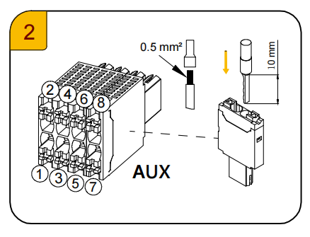
Figure 6-23 A 6-pin terminal block with AUX connection
In emergency situations, such as fire, the end user can manually press the EPO (Emergency Power Off) button to shut down the inverter and switch off the battery (except for the PV array). End users or installer should prepare the external EPO.
AUX cable requirements: outdoor shielded copper cable (flexible); recommended conductor cross-section 0.5 mm2; conductor ends should be fitted with bootlace ferrules.
To disconnect the AUX connection, rotate the handles on both sides clockwise, unplug the AUX connector, insert a screwdriver (blade width: 1.2 mm) into the relative connection position side and unplug the conductor.
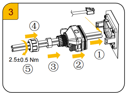
Figure 6-24 Disconnect the AUX connection
3. Place the COM connection cover against the inverter enclosure and tighten the 4 screws. When securing the cover over the communication ports, tighten the cover in place and then lightly push the communication cables into the cover as you tighten the strain relief nuts onto the cables. This will ensure the communication cables are well-seated in the RJ45 ports.
The pin definition of the communication ports:
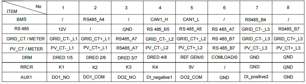
Mount the Covers of the Inverter and Battery
After finishing electrical connection of energy storage system, please follow the steps below.
1. Mount the cable cover of the battery, Refer to 1-2 in Figure 6-25.
Cut a cable hole based on the cabling routing and route the cables through the cable hole.
Align the top surface of the cable cover to the top surface of the battery housing.
Align the protrusions on the right side of the cable cover to the slots on the left side of the battery’s front cover, then push the cable cover right to the battery housing till hearing the "click" sound.
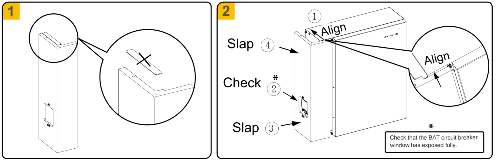
Figure 6-25 Install the cable cover for the battery
- Disassemble the cable cover of the battery, Refer to 1 in Figure 6-26.
- Grasp the cable cover, then pull it to the left.
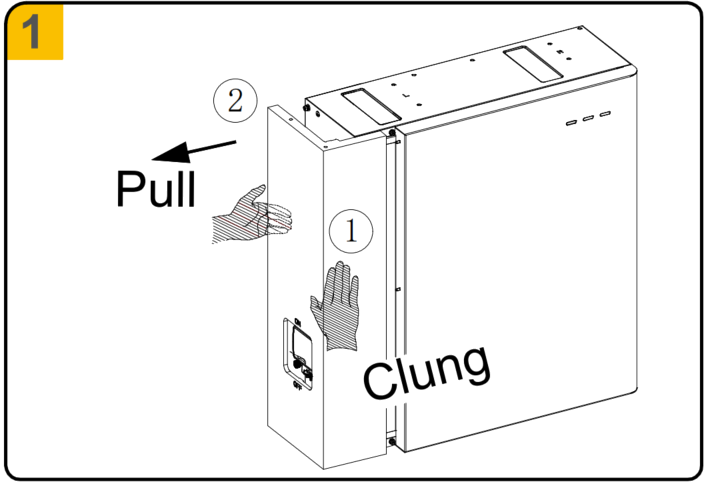
Figure 6-26 Disassemble Cable Cover
- Mount the covers of the inverter
- Attach the top cover to the inverter.
Place the top cover on top of the inverter and slide it forward. The three side screws of the top cover should align to the inverter mounting threaded holes. Secure the top cover to the inverter (tool: T20 screwdriver, torque: 1.6 Nm).
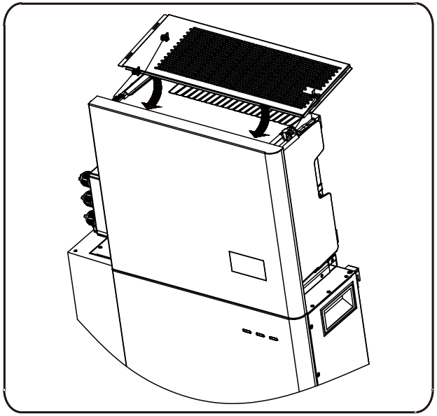
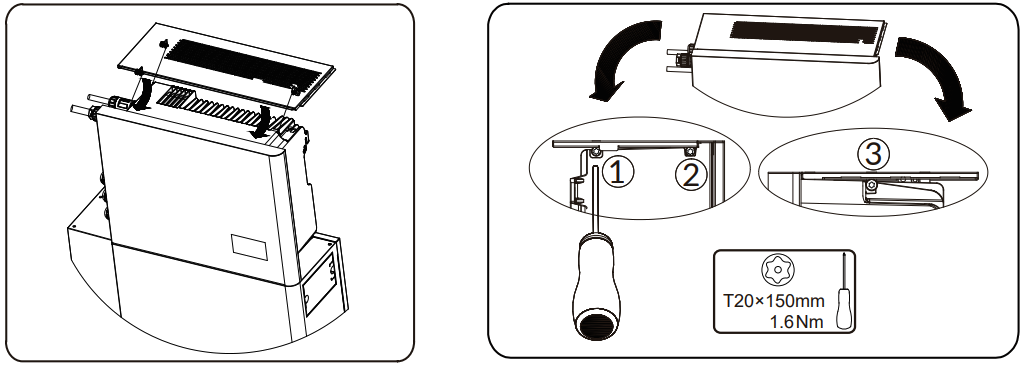
Figure 6-27 Attach the top cover to the inverter
- Mount left cable cover and right cover of the inverter when inverter standing on the battery, please follow the steps below.
Take out the right cover and cable cover from the inverter packaging.
Align the hooks on the front side of the right cover to the slots on the right side of the front cover, downwards insert the right cover along the right edge of the inverter front cover till the protruding pin in the lower right corner falls into the hole located at the right rear of the battery housing.
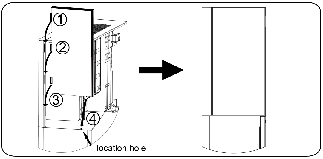
Figure 6-28 Mount the right cover
- Cut a cable hole based on the AC cabling routing and route the cables through the cable hole.
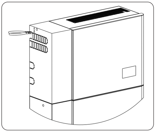
Figure 6-29 Cut a cable hole
- Align the hooks on the right side of the cable cover to the slots on the left side of the front cover, downwards insert the cable cover along the left edge of the inverter front cover till the top surfaces of the top cover and cable cover are flush.
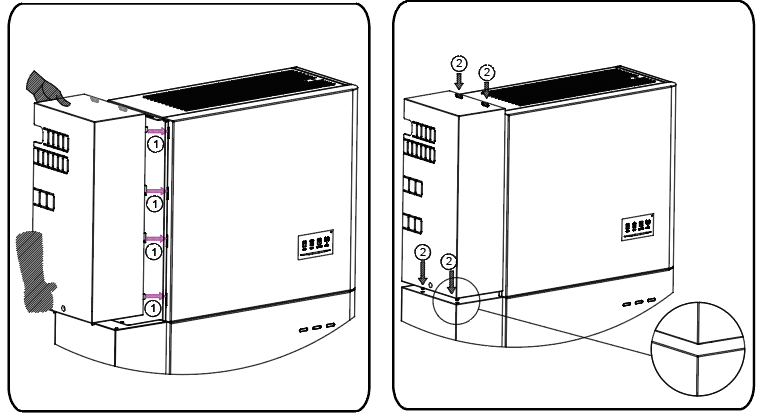
Figure 6-30 Mount the cable cover
- Disassemble the cable cover of the inverter
Insert a screwdriver (blade width: 1.2 mm) into the gap between the cable covers of the inverter and the first battery, then pry the cable cover up lightly.
Grasp the cable cover and lift it up by about 20mm, then move it to the left.
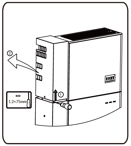
Figure 6-31 Disassemble the cable cover of the inverter