

Maintenance and Troubleshooting
Routine Maintenance
Normally, the energy storage system needs no maintenance or calibration.
However, in order to maintain the accuracy of the SOC, it is recommended to perform a full charge calibration for SOC (charge the battery until the charge power is 0W) on the battery at regular intervals (such as two weeks).
Before cleaning, ensure that the system is disconnected from all power sources. Clean the housing, cover and display panel with a soft cloth.
To ensure that the energy storage system can operate properly in the long term, it is advised to perform routine maintenance as described in this chapter.
Maintenance Checklist
Check Item | Acceptance Criteria | Maintenance Interval |
Product cleanliness | The enclosure of the inverter should be free from obstacles or dust. | Once every 6 to 12 months |
Product visible damage | The product should be not damaged or deformed. | Once every 6 months |
Product running status | 1. The product should operate without any abnormal sound. 2. All parameters of the product should be set correctly. Perform this check when the product is running. | Once every 6 months |
Electrical connections | 1. Cables should be securely connected. 2. Cables should be intact, and in particular, the cable jackets touching the metallic surface should not be scratched. 3. Unused cable glands should be blocked by rubber sealing which are secured by pressure caps. | Perform the first maintenance 6 months after the initial commissioning. Thereafter, perform the maintenance once every 6 to 12 months. |
WARNING
Risk of burns due to hot enclosure of the inverter
The enclosure of the inverter can get hot during operation.
Do not touch any parts other than the display panel during operation.
Wait approximately 30 minutes for the inverter to cool down before cleaning.
Troubleshooting
Common Errors

Communication Troubleshooting
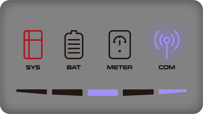
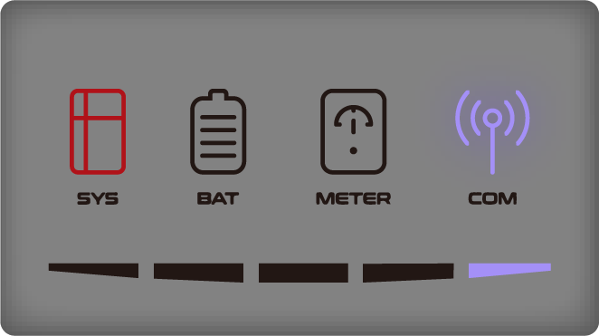
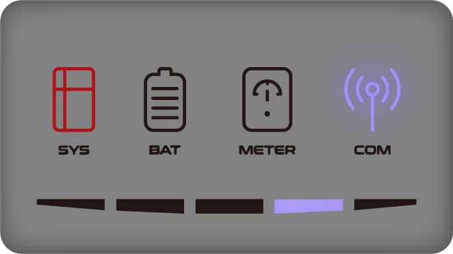
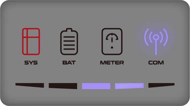
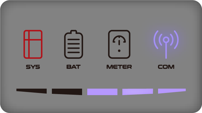
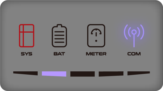
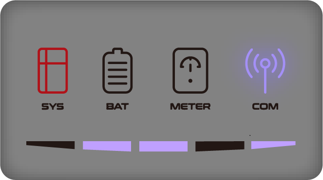
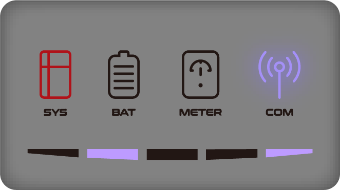
LED Indicator | Error Code | LED Display | Description | Troubleshooting |
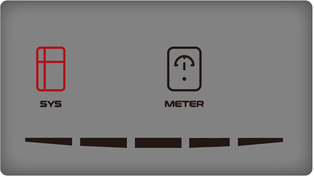
SYS red light is flashing fast | 4 |
| Inverter lost | Inverter communication lost 1. Restart the system. 2. Contact customer service to remotely update the inverter program. 3. If the error persists, contact customer service for further check. |
METER light is off if all meters lost. | 5 |
| Grid meter lost | Grid side meter lost 1. Check whether the system configuration parameters of the AlphaESS App or AlphaCloud are correct and whether the meter is used on the grid side. 2. Check whether the communication cable of the grid meter is connected correctly (RS485:3A6B). 3. Check whether the communication configuration parameters of the grid meter are correct (communication address and baud rate). 4. If the error persists, contact customer service for further check. |
6 |
| PV meter lost | PV inverter side meter lost 1. Check whether the system configuration parameters of the AlphaESS App or AlphaCloud are correct and whether the meter is used on the PV inverter side 2. Check whether the communication cable of the meter of PV inverter side is connected correctly (RS485:3A6B). 3. Check whether the communication configuration parameters of the meter on the PV inverter side are correct (communication address and baud rate). 4. If the error persists, contact customer service for further check. | |
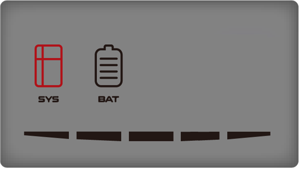
SYS red light is glowing, BAT light is off | 7 |
| BMS lost | BMS lost 1. Check whether the BMS communication connection between the battery and the inverter is correct. 2. Check if the battery is switched on. 3. If the error persists, contact customer service for further check. |

Battery Error Troubleshooting
LED Indicator | Error Code | LED Display | Description | Troubleshooting |
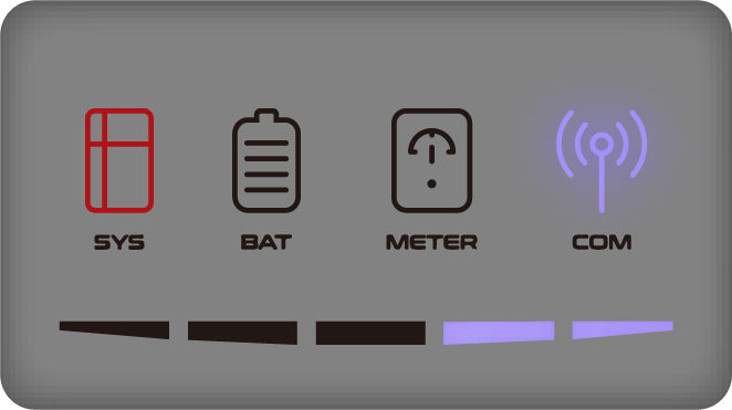
| 60002 |
| Circuit_Breaker_ Open | Try to switch on all batteries’ circuit breakers. If the error persists, contact customer service for further check. |
60004 |
| Follower_ Battery_ Communication_Lost | Check the communication cables between batteries. If the error persists, contact customer service for further check. | |
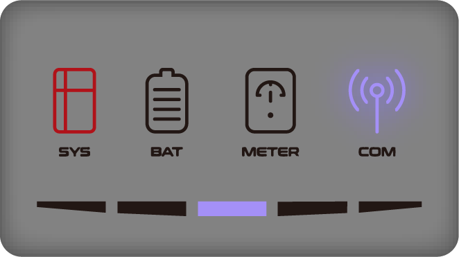
60006 |
| Host_Battery_ Communication_ Lost | ||
60008 |
| Multi_Host_ error |

Inverter Error Troubleshooting
LED Indicator | Error Code | LED Display | Description | Troubleshooting |
| 100000 |
| Grid_OVP |
3. Restart inverter. If the error persists, contact customer service for further check. |
100001 |
| Grid_UVP |
If the error persists, contact customer service for further check.
If the error persists, contact customer service for further check. | |
100002 |
| Grid_OFP | ||
100003 |
| Grid_UFP | ||
100005 |
| BUS_OVP1 | ||
100007 |
| Insulation_ fault |
2. Check whether PV cable is damaged. If the error persists, contact customer service for further check. | |
100008 |
| GFCI_fault | 1. Restart inverter and check whether the error persists. If so, please call customer service. | |
100010 |
| Grid_relay_ fault | ||
100011 |
| Over_ Temperature |
2. Confirm whether inverter installation meets the installation requirements. | |
100012 |
| PV_Reverse |
| |
100013 |
| BAT_Reverse |
| |
100017 |
| MPPT1_OVP | Check the PV1 voltage. If it exceeds 950VDC, reduce the number of PV modules. | |
100021 |
| MPPT2_OVP | Check the PV2 voltage. If it exceeds 950V, reduce the number of PV modules | |
100025 |
| BAT_OVP | Check whether the actual battery voltage exceeds the battery charge cut-off voltage by more than 20V. | |
100026 |
| BAT_UVP | 1. Check whether the actual battery voltage is lower than the battery discharge cut-off voltage. If the error persists, contact customer service for further check. | |
100027 |
| Battery_lose | 1. Confirm whether the battery communication cable connection is normal. 2. check whether the battery voltage sampling value is less than 75V. If the error persists, contact customer service for further check. | |
100042 |
| Output_short_ circuit | 1. Use a multimeter to test the impedance of the off-grid output. If it is low, check whether the wiring is correct. 2. Restart the inverter. If the error persists, contact customer service for further check. | |
100043 |
| Output_ overload |
2. Restart the inverter. If the error persists, contact customer service for further check. | |
|
|
| 1. Restart the inverter.
| |
|
|
| ||
|
| Check the inverter software versions. If they are inconsistent, upgrade the inverters to the same software version. | ||
|
|
|
| |
|
|
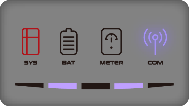
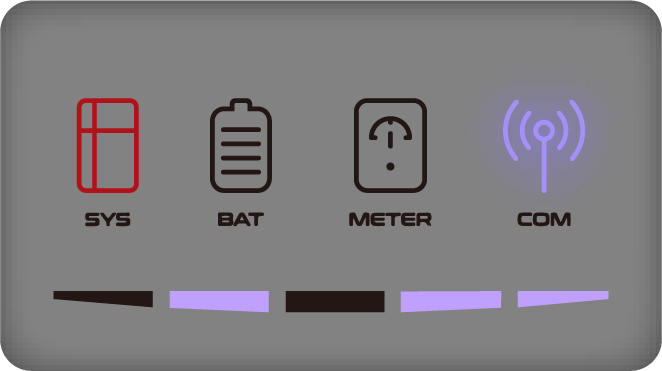
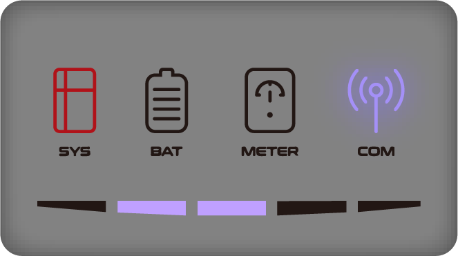
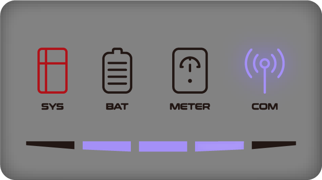
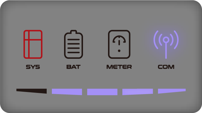
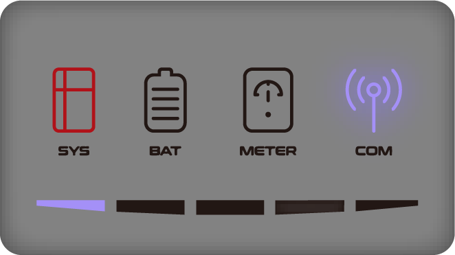
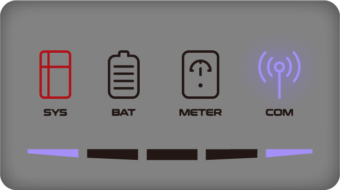
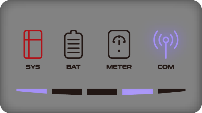
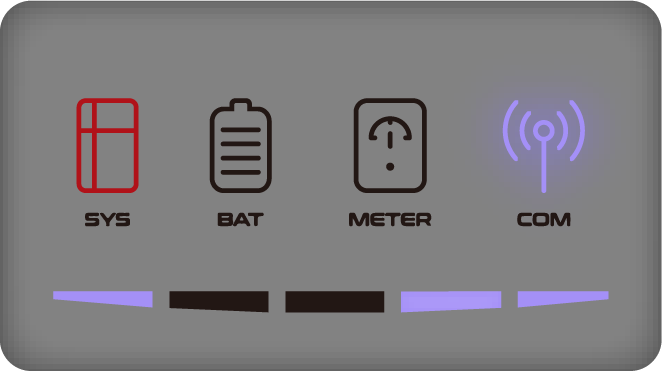
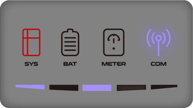
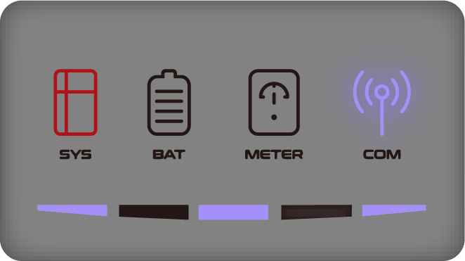
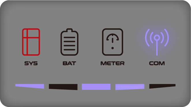
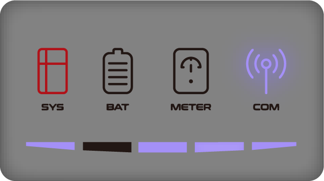
Accessories Error Troubleshooting
LED Indicator | Error Code | LED Display | Description | Troubleshooting |
SYS red light is on, METER light is flashing fast. SYS red light is on, METER light is flashing fast. | 39 |
| EV Charger Lost | EV Charger lost
If the error persists, contact customer service for further check. |
200000 |
| Relay OTP | 1. Unplug the charging connector of the EV charger, and wait for about 10 minutes before plugging it back in. If the error persists, contact customer service for further check. | |
200001 |
| Output overload | 1. Check whether the load exceeds the rated power. 2. Restart the inverter. If the error persists, contact customer service for further check. | |
200010 |
| AC leakage current | 1. Unplug the charging connector of the EV charger, and wait for about 10 minutes before plugging it back in. If the error persists, contact customer service for further check. | |
200011 |
| Input terminal OTP | 1. Unplug the charging connector of the EV charger, and wait for about 10 minutes before plugging it back in. If the error persists, contact customer service for further check. | |
200014 |
| Relay abnormal | 1. The EV charger has a hardware failure and need to be replaced, please contact customer service. | |
200015 |
| Ground fault | 1. Check whether the grounding method is correct. If there is no grounding or the grounding method is wrong, please follow the correct grounding method. | |
200016 |
| Reverse phase | 1. Shut off the leakage current protection switch of the power distribution cabinet immediately. 2. Check whether the AC input/output cable connection is normal, and verify whether there is an inverse connection of L/N input cables. |
Battery Protection Description for Series Battery
The three LED indicators on the front cover provide information about the protection status of the battery.

: Yellow LEDs flashing

: Yellow LEDs on

: Yellow LEDs off
LED Display State | Description | Troubleshooting |
| Temperature difference | Wait for automatic recovery. If this protection state persists, please call customer service. |
| High temperature | Stop discharging and charging until this protection state disappears. Wait for the temperature to drop. |
| Low temperature discharge | Stop discharging until this protection state disappears. Wait for the temperature to rise. |
| Overcurrent charge | Wait for automatic recovery. If this protection state persists, please call customer service. |
| Overcurrent discharge | |
| Cell overvoltage |
|
| Cell under voltage | Stop discharging and call customer service immediately. |
| Low temperature charge | Stop charging until this protection state disappears. Wait for the temperature to rise. |



During work mode, if the protection status “Cell under voltage”
appears, please take the following action:
First, switch off the circuit breaker which is located at the lower left of the battery, switch on the circuit breaker and wait for 3~5s, switch off the circuit breaker, then switch on the circuit breaker and wait for 3~5s, switch off the circuit breaker, at last switch on the circuit breaker of the battery. The BMS will be forced to turn on the MOSFET of discharge, allowing the energy storage inverter to detect the battery’s open voltage and begin charging it.
**
Battery Error Description
The three LED indicators on the front cover provide information about the error
status of the battery.

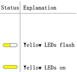
LED Display State | Description | Troubleshooting |
| Hardware error | Wait for automatic recovery. If this error persists, please call customer service. |
| Hardware error | |
| Circuit breaker open | Switch on circuit breaker after power off the battery. |
| LMU disconnect (follower) | Reconnect the BMS communication cable. |
| SN missing | Please call customer service. |
| LMU disconnect (host) | Reconnect the BMS communication cable. |
| Software version inconsistent | Please call customer service. |
| Multi-host | Restart all batteries. |
| MOS over temperature | Power off the battery and power on the battery after 30 minutes. |
| Insulation fault | Restart battery. In case this error persists, please call customer service. |
| Total voltage fault | Restart battery. In case this error persists, please call customer service. |
| Precharge failure | Restart battery. In case this error persists, please call customer service. |


